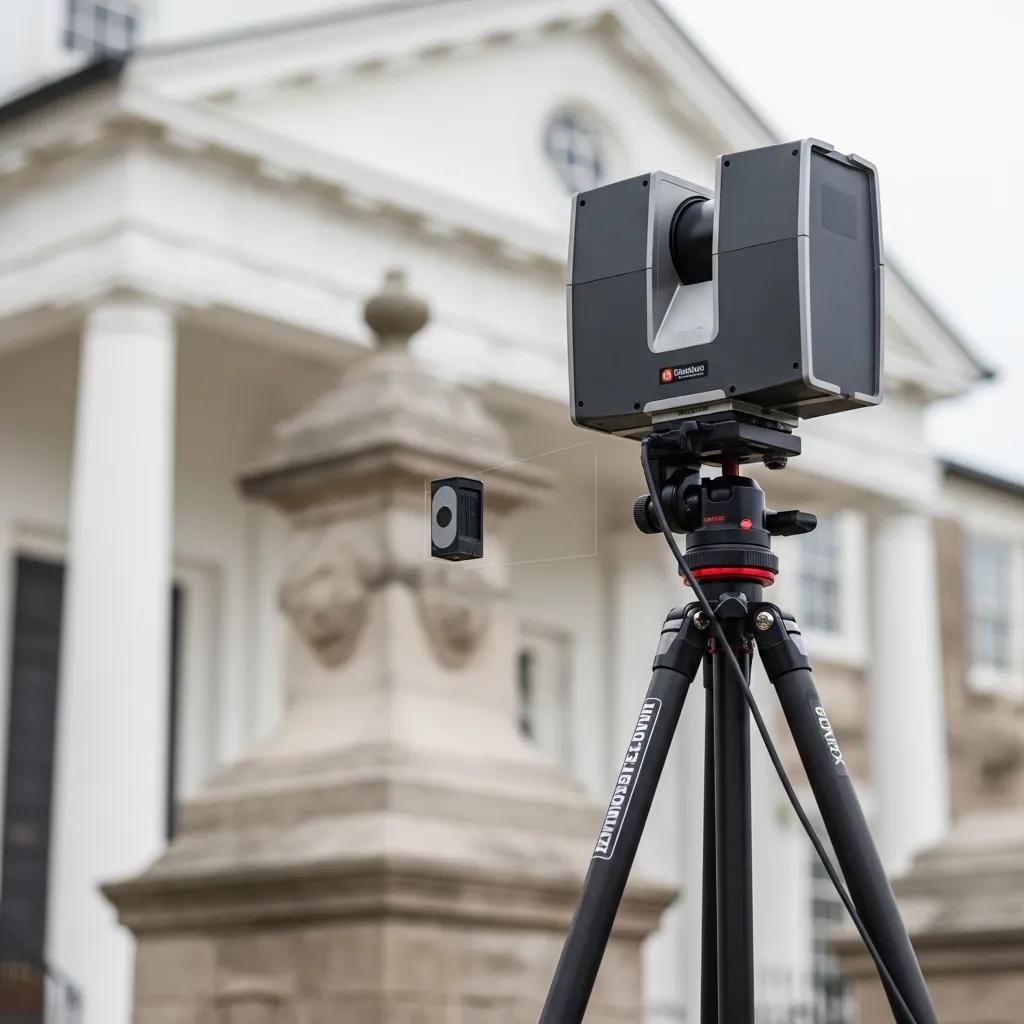
3D Scanning for Renovation Projects in Charleston, SC: Precise As‑Built Data and BIM Integration
3D scanning produces accurate, measurable as‑built records so architects, engineers, and contractors can design and coordinate retrofits with far fewer assumptions. Charleston’s renovation work often includes irregular historic geometries, tight urban sites, and strict preservation rules — conditions that make millimeter‑level surveys essential to lower risk and meet compliance. This article outlines how terrestrial laser scanning and LiDAR generate point clouds and scan‑to‑BIM deliverables that plug directly into BIM and VDC workflows to reduce rework and shorten schedules. You’ll find the core benefits of laser scanning for retrofit projects, a practical overview of the scanning process and typical hardware, the standard deliverables and how teams use them on site, and how scanning supports historic preservation and complex MEP coordination in Charleston. Practical checklists, process tables, and deliverable comparisons are included to simplify procurement and show when to request professional scanning services in the Charleston area.
Why 3D Laser Scanning Is the Right Choice for Charleston Renovations
Terrestrial LiDAR (3D laser scanning) records dense point clouds that represent existing conditions with millimeter‑level accuracy, so designers base retrofit decisions on measured reality instead of assumptions or incomplete drawings. A scanner emits laser pulses, measures returns, and builds positionally accurate point clouds that are georeferenced and registered into a single coordinated dataset. The upshot is fewer assumptions in design, reduced RFIs during construction, and measurable cuts in rework and schedule risk — especially on Charleston projects with concealed MEP, irregular historic detail, or tight tolerances. Where geometry is irregular, access is constrained, or preservation rules are strict, scanning delivers the most reliable foundation for retrofit work.
Key operational advantages of 3D scanning:
- Millimeter verification: captures true geometry for precision retrofit work.
- Faster field surveys: reduces on‑site hours while delivering richer data.
- Better coordination: supports clash detection and prefabrication planning.
Those advantages translate into avoided costs and compressed schedules for Charleston renovation teams, and they shape how providers collect, process, and hand off usable deliverables for BIM and construction coordination.
Conway Coordination and Layout Services (CCLS) combines local, family‑owned experience with focused reality‑capture workflows across the Southeast, pairing high‑precision Trimble and LiDAR hardware with VDC/BIM integration so scan data flows cleanly into client models. That regional familiarity matters in Charleston, where preservation requirements and multi‑party coordination are routine.
What Are the Primary Benefits of 3D Scanning for Renovation?
3D scanning supplies actionable as‑built data that reduces uncertainty and supports better decisions through design and construction. Point clouds remove guesswork by giving architects and engineers precise measurements, increasing design confidence and cutting the number of field verification trips. Early‑phase coordination speeds up because teams can measure and visualize remotely, enabling trade contractors to prefabricate components and plan sequences with fewer surprises. Reality capture also improves safety by limiting the need for personnel in confined or hazardous spaces, and it creates a permanent digital record for future maintenance or modifications. In short: accuracy, speed, safety, and archival value make 3D scanning a practical investment for Charleston retrofits where hidden conditions or historic detail raise project risk.
How 3D Scanning Improves Accuracy and Reduces Rework
Registered point clouds provide an objective baseline to validate designs before construction, closing the information gap that often triggers clashes and change orders. When teams import scans into BIM they can run clash detection and spatial validation against proposed MEP routes, structural changes, and envelope work — resolving conflicts digitally instead of in the field. That pre‑construction verification lowers RFI volume and rework costs, and it enables prefabrication by supplying exact geometries for off‑site fabrication of ductwork, piping, and modular assemblies. Projects that adopt scan‑to‑BIM workflows usually report fewer coordination delays and reduced contingency spend because assumptions are replaced with measured reality, protecting both budget and schedule for complex Charleston renovations.
How CCLS Delivers Precise 3D Scanning Services in Charleston

Turning raw scan captures into usable BIM and coordination deliverables requires a clear, repeatable workflow. We start with scope definition, access planning, and control placement so scans tie to project coordinates, then proceed through on‑site capture, registration, QA, and final deliverable production. Each step ties tools and team roles to expected outputs, giving reliable timelines and predictable handoffs for architectural and MEP teams. Laying out these steps against deliverables clarifies responsibilities and removes uncertainty about what the client receives and when.
The typical project process and outputs are summarized below.
| Phase | Tools / Team | Output / Typical Turnaround |
|---|---|---|
| Project kickoff & scoping | Project manager, surveyor, BIM coordinator | Scope letter, site access plan, estimated schedule |
| On-site scanning & control | TLS/LiDAR, target control, handheld scanners | Registered scans (raw data) captured in 1–3 days depending on size |
| Processing & registration | Point‑cloud software, QA engineer | Cleaned, registered point cloud and QA report |
| Deliverable creation & BIM integration | BIM modelers, CAD technicians | Scan‑to‑BIM model, 2D CAD extractions, coordination reports |
This sequence shows how each phase produces distinct outputs that feed the next phase of the renovation workflow. Below we walk through the step‑by‑step actions typical on a Charleston renovation.
Step‑by‑Step: The 3D Scanning Process for Renovations
A standard scanning engagement follows clear, verifiable steps so all stakeholders share expectations and deliverables. First, we define scope and access needs, review any existing drawings, and identify coordination points to minimize surprises. Second, technicians deploy terrestrial scanners and control points to capture overlapping scans, supplementing with handheld LiDAR in confined or decorative spaces. Third, captured data is registered, georeferenced, filtered for noise, and QA‑checked to ensure positional integrity. Fourth, we produce deliverables — point clouds, orthophotos, 2D CAD extractions, and scan‑to‑BIM models — and review them with the project team for acceptance before handoff. This staged approach reduces risk and aligns outputs with BIM/VDC workflows.
Technologies and Equipment That Deliver High‑Resolution Scans
High‑resolution results depend on choosing the right hardware and software for each task. Terrestrial laser scanners provide the highest absolute accuracy for open spaces and structural elements; mobile mapping systems and handheld LiDAR efficiently capture corridors, stairways, and ornate features. Photogrammetry complements LiDAR when high‑resolution color and texture matter for façades or archival records. Processing software handles registration, noise reduction, and export to industry formats compatible with Revit, Navisworks, and other BIM platforms, ensuring smooth integration into design and coordination pipelines. Picking the correct toolset preserves accuracy while optimizing time on site.
Essential Deliverables from 3D Scanning for Renovation
Clients need clarity about what they’ll receive and how those files support design, permitting, and construction coordination. Typical deliverables include raw and cleaned point cloud datasets, scan‑to‑BIM models at defined levels of detail, 2D CAD extractions for permit drawings, orthophotos for façade documentation, and coordination reports such as clash detection summaries. Each deliverable serves different project stakeholders: architects use point clouds for validation, MEP contractors use BIM models for prefabrication, and owners keep archival datasets for facilities management. Presenting deliverables side‑by‑side helps design teams and owners choose the right package for their goals.
| Deliverable | Format / LOD | Typical Use |
|---|---|---|
| Point cloud dataset | LAS / E57; native scanner files | Measurement verification, remote takeoffs, archival record |
| Scan‑to‑BIM model | Revit LOD 200–300 | Coordination, clash detection, prefabrication |
| 2D CAD extractions | DWG / PDF | Permit drawings, retrofit construction documents |
| Orthophotos & elevations | GeoTIFF / JPEG | Façade documentation, material analysis |
In short: point clouds preserve raw reality, BIM models translate geometry into parametric elements, and CAD extracts serve permitting and plan‑set needs. The section below explains how different stakeholders use these outputs in practice.
How Point Cloud Data and As‑Built Documentation Are Used
Point clouds act as an objective reference for measurement, verification, and design decisions across project phases. Architects import point clouds into modeling environments to validate as‑built geometry and dimension spaces without repeated site visits, streamlining early design and lowering RFI counts. MEP contractors use scans to plan routing and prefabrication, minimizing clashes and waste during installation. Facility managers retain scan data as an archival baseline for future renovations and asset tracking. Because point clouds are interoperable with BIM and CAD tools, they bridge field reality with digital design and long‑term asset management.
What Scan‑to‑BIM Means for Charleston Renovations
Scan‑to‑BIM converts registered point clouds into modeled building elements at specified levels of detail — commonly LOD 200 for conceptual retrofit work and LOD 300 for construction‑level coordination. Modeled geometry replaces assumptions and supports clash detection, precise prefabrication, and contractor submittals. In Charleston, scan‑to‑BIM helps reconcile irregular historic geometry and ensures modern system insertions respect original fabric. Accurate scan‑to‑BIM models cut change orders by giving designers and subcontractors measurable components they can rely on throughout construction.
How 3D Scanning Supports Historic Preservation in Charleston

3D scanning captures architectural detail non‑invasively, creating archival‑grade datasets for restoration, replication, and structural analysis. Dense point clouds record decorative features, irregular profiles, and hidden structural interfaces with high fidelity so conservators can study geometry without touching fragile fabric. That capability is vital in Charleston, where preservation rules and community expectations favor minimally invasive documentation and repeatable records. Scanning also enables virtual reconstruction for interpretive displays and allows fabricators to produce replacement components that match original profiles precisely.
Common preservation challenges and how scanning responds:
| Preservation Challenge | Typical Constraint | How 3D Scanning Helps |
|---|---|---|
| Decorative, non‑orthogonal geometry | Fragile surfaces | High‑density point clouds capture detail without contact |
| Restricted access | Scaffolding limitations | Handheld LiDAR and photogrammetry reach tight areas quickly |
| Material variability | Low laser reflectivity | Combined LiDAR + photogrammetry improves model completeness |
These examples show scanning workflows can be tailored to minimize impact while maximizing archival value for Charleston’s historic built environment. The following section addresses specific challenges posed by older structures and common mitigation strategies.
Challenges Historic Buildings Present for Renovation Scanning
Historic structures often have irregular geometry, delicate materials, and access constraints that complicate standard scanning protocols. Non‑orthogonal walls, ornamental cornices, and thin masonry require careful scanner placement and sometimes higher‑density capture or photogrammetric texture to preserve fidelity. Access restrictions — physical or regulatory — may limit tripod placement or require off‑hours work, increasing coordination needs. Surfaces that are dark, glossy, or low‑reflectivity can reduce laser returns, so mixed‑method captures and post‑processing strategies are used to create a complete dataset while protecting sensitive fabric.
How 3D Scanning Helps Preserve Charleston’s Architectural Heritage
By producing accurate digital twins, 3D scanning supports restoration decisions, component replication, and public interpretation without further stressing historic materials. Scans let fabricators produce replacement elements from precise geometry, reducing on‑site trial‑and‑error. Archival models also help structural analysts track deformation or movement over time, enabling preventive conservation. Virtual reconstructions derived from scan data can be shared with stakeholders and the public so interventions are visualized before work begins and the building’s condition is documented for future generations.
Which Renovation Scenarios Gain the Most from 3D Scanning in Charleston?
Certain renovation types get outsized value from reality capture because of complexity, tight tolerances, or preservation status. MEP upgrades in occupied buildings often require exact clearances and prefabrication; commercial tenant fit‑outs need fast, reliable baseline data to meet tight lease schedules; and adaptive reuse of historic properties requires detailed documentation to integrate modern systems with legacy construction. In these scenarios, scan‑to‑BIM workflows reduce surprises, speed coordination, and improve predictability of cost and schedule.
Common renovation scenarios that benefit include:
- MEP upgrades and coordination: precise geometry enables accurate routing and prefabrication.
- Commercial modernization and tenant fit‑outs: rapid surveys compress planning time.
- Adaptive reuse and historic preservation: detailed documentation protects original fabric.
Choosing scanning when these conditions apply can materially reduce contingency and rework. The table below links typical renovation challenges to practical scanning solutions.
| Renovation Scenario | Typical Challenges | How 3D Scanning Addresses Challenge |
|---|---|---|
| MEP upgrades | Hidden ceilings, congested risers | Provides exact spatial clearance for prefabricated assemblies |
| Commercial modernization | Multiple tenants, tight schedules | Enables remote coordination and faster tenant fit‑out design |
| Adaptive reuse | Irregular structures, preservation limits | Records existing fabric and supports non‑invasive interventions |
That mapping explains why design and construction teams increasingly specify reality‑capture deliverables for Charleston retrofit work, particularly when prefabrication and clash avoidance are priorities. The next subsection explains how scanning specifically supports MEP coordination.
How 3D Scanning Supports MEP Upgrades and Coordination
Accurate scan data removes ambiguity around conduit, duct, and piping routes so contractors can model and prefabricate systems off‑site with confidence. During coordination, point clouds are referenced in BIM to detect clashes among MEP trades and with structural elements, letting teams resolve interferences before fabrication or installation. This reduces on‑site rework and labor because prefabricated modules fit the verified space. On Charleston projects with limited access, prefabrication based on scan data shortens on‑site installation windows and lowers disruption.
Advantages for Commercial Building Modernization
Commercial modernization gains from rapid reality capture that establishes a verifiable baseline for permitting, tenant planning, and phased fit‑outs. Scan‑derived models cut the number of site visits needed by enabling remote measurements and virtual sign‑offs, speeding tenant coordination and reducing occupant disruption. Accurate as‑built data lowers contingency in cost estimates and supports phased construction where sequencing is critical. For owners and developers, these efficiencies mean faster tenant readiness and improved return on investment.
How to Request a Consultation for Renovation Scanning Services
To scope, price, and schedule a scanning engagement quickly, providers need a concise set of project inputs. Prepare the project address, a high‑level scope (areas to be scanned and desired deliverables), any existing plans or photos, access constraints, and key schedule milestones. Supplying these items up front lets vendors deliver targeted proposals that align deliverables (point cloud, scan‑to‑BIM, CAD extractions) to project needs and reduces back‑and‑forth during procurement. The checklist below helps teams assemble the information needed for a timely, accurate quote.
Checklist to start a scanning project:
- Project address and brief building description
- Desired deliverables (point cloud, BIM LOD target, CAD sheets)
- Photos, existing drawings, and site access notes
- Key deadlines and a single point‑of‑contact for site coordination
Providing this information shortens lead time and clarifies expectations. The section below explains what details scanning teams need to prepare an estimate and how CCLS supports professional clients in Charleston.
What Information Do We Need to Start a 3D Scanning Project?
To produce an accurate scope and estimate, scanning teams need enough context to identify access requirements and deliverable formats. Share the building address, a brief scope (floors, zones, or systems to be scanned), any available plans or photos, and scheduling constraints such as occupancy windows or preservation‑related timing. Note restricted areas or permissions required for historic sites to avoid delays. Naming a single point‑of‑contact who can grant access and answer technical questions streamlines mobilization and reduces the risk of scope changes after mobilization.
How CCLS Supports Construction and Engineering Teams in Charleston
Conway Coordination and Layout Services (CCLS) delivers precise reality‑capture packages tuned to BIM and VDC workflows so data integrates seamlessly into clients’ existing models and coordination platforms. We emphasize precise control methods and local mobilization, pairing Trimble‑grade surveying with deliverable options such as raw point clouds, scan‑to‑BIM models, and CAD extractions for permitting and construction. Key benefits for engineering and construction teams include:
- Deliverables aligned with BIM LOD expectations and coordination needs.
- Local presence for responsive mobilization and in‑person site coordination.
- Workflows built to reduce rework and support prefabrication‑led schedules.
If you’re preparing an RFP, assemble the checklist above and request a consultation with Conway Coordination and Layout Services to confirm scope, timing, and deliverable formats. We’ll recommend the most efficient capture strategy for your Charleston renovation while respecting preservation and coordination constraints.
- Prepare project context: Gather address, photos, and scope.
- Specify deliverables: Point cloud, BIM LOD, and CAD outputs.
- Request consultation: Share the checklist and schedule a scope review with CCLS to confirm logistics and timing.
Following these steps helps procurement and technical teams quickly evaluate the value of reality capture and move to a scoped, priced engagement.
Frequently Asked Questions
Which projects get the most value from 3D scanning in Charleston?
3D scanning is particularly helpful on complex Charleston renovations such as MEP upgrades, multi‑tenant commercial fit‑outs, and adaptive reuse of historic buildings. These jobs often include intricate geometry, tight tolerances, and preservation constraints. By delivering precise as‑built data, scanning reduces uncertainty, streamlines coordination, and helps integrate modern systems without compromising historic fabric.
How does 3D scanning affect project timelines?
3D scanning accelerates timelines by reducing repeated site visits and minimizing rework. Accurate point clouds let teams make informed design decisions earlier, which streamlines coordination across stakeholders. That efficiency is especially valuable in Charleston, where regulatory windows and preservation considerations can tighten schedules. Faster data collection and analysis typically translate into quicker project delivery.
What are the cost implications of using 3D scanning?
While scanning has an upfront cost, the long‑term savings can be significant. Accurate as‑built data reduces unexpected change orders and rework, improves coordination among trades, and shortens installation time through prefabrication. For complex Charleston renovations, the return on investment from scanning often outweighs the initial expense by lowering contingency and schedule risk.
Can 3D scanning be used for both interior and exterior work?
Yes. 3D scanning is versatile for interior and exterior renovations. Indoors, it captures tight, intricate details; outdoors, it documents façades and context. That adaptability makes scanning a valuable tool for Charleston projects where both interior systems and exterior preservation may be part of the scope.
What software is commonly used with 3D scanning data?
Scan data is processed with tools that handle point clouds and export to BIM platforms. Common software includes Autodesk Revit and Navisworks, as well as point‑cloud specialists like Cyclone and CloudCompare. These applications let teams visualize, analyze, and integrate scanned data into design and construction workflows for effective project execution in Charleston.
How does 3D scanning help meet local preservation requirements?
3D scanning produces detailed, non‑invasive documentation that supports compliance with preservation guidelines. High‑resolution datasets allow architects and engineers to design interventions that respect original fabric and produce well‑documented plans for review. In Charleston, where preservation standards are strict, scanning helps smooth approvals and reduces the risk of non‑compliance by providing clear, defensible documentation.
Conclusion
Using 3D scanning for Charleston renovation projects delivers accuracy, efficiency, and strong support for historic preservation — all of which help projects run with fewer surprises and tighter schedules. The technology reduces rework, enhances collaboration among stakeholders, and creates durable records for future use. For precision scanning and BIM integration that respect Charleston’s historic context, contact Conway Coordination and Layout Services to discuss a tailored capture strategy for your renovation.