
MEP BIM Modeling Services in Savannah, GA — Precise Coordination for Predictable, On‑Time Delivery
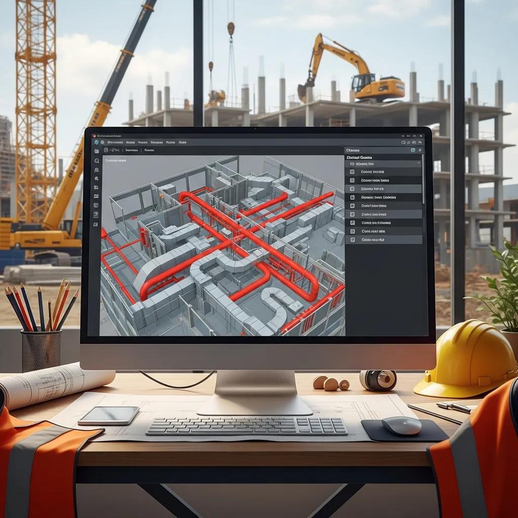
MEP (mechanical, electrical, plumbing) Building Information Modeling (BIM) delivers coordinated, data-rich models that help teams find clashes early, quantify materials, and guide accurate installation from design through commissioning. Below we explain how disciplined MEP BIM modeling and coordination reduce rework, shorten schedules, and improve cost certainty for projects in Savannah and the surrounding region. You’ll find trade-specific benefits, a typical clash-detection workflow, and how scan-to-BIM plus precise field layout connect the digital model to what gets built on site. If you’re a local contractor, engineer, or owner tackling renovations, historic restorations, or tight urban sites, this practical overview shows how BIM de-risks projects and produces prefabrication- and fabrication-ready outputs. The sections that follow cover core benefits, HVAC/plumbing/electrical details, local service options, enabling technology, an end-to-end process from concept to as-built, VDC integration, and common technical questions about tools and Level of Development (LOD).
Conway Coordination and Layout Services (CCLS) is a Savannah-based provider offering BIM modeling and coordination, 3D scanning, VDC consulting, and survey-grade field layout — services that tie model geometry to construction execution. We follow industry-standard BIM workflows and pair them with field technology to deliver fabrication-ready files and to validate installations on site, smoothing handoffs between design, fabrication, and crews. Continue for concise checklists, a step-by-step process guide, and clear tables that map services to deliverables and client outcomes for easy decision-making on local projects.
Why MEP BIM Modeling Matters for Construction in Savannah
MEP BIM gives project teams a single authoritative model for mechanical, electrical, and plumbing systems so spatial conflicts are identified early and their schedule and cost impacts can be measured. When discipline models are aggregated into a federated model, clashes are found before crews arrive, improving constructibility and cutting RFIs during installation. Savannah projects often involve retrofits and historic elements; BIM provides accurate context for routing and prefabrication so teams avoid on-site surprises. The next section explains trade-specific gains for HVAC, electrical, and plumbing, and how those gains stack up when coordination is done across trades.
MEP BIM produces repeatable outputs that translate into measurable project improvements:
- Less rework and fewer RFIs through early clash resolution and verified clearances.
- More predictable schedules through prefabrication and better sequencing.
- Tighter cost control thanks to accurate quantity take-offs and material lists.
Together, those benefits turn BIM into a practical risk‑reduction strategy that improves installation accuracy and operational readiness for owners.
How MEP BIM Coordination Helps Mechanical, Electrical, and Plumbing Systems
Coordination in a BIM environment ensures each trade’s geometry, clearances, and system requirements are reconciled before field work begins—making systems easier to install. For HVAC, BIM streamlines duct routing, reduces complex transitions that hurt airflow, and resolves clashes with structure and architecture. Electrical modeling clarifies conduit and tray runs, panel locations, and lighting layouts to meet code and serviceability needs while avoiding late design shifts. Plumbing coordination verifies slopes, drainage routes, and fixture connections so prefabricated spools fit as intended. These trade-level improvements cut field labor hours and compress commissioning by preventing the surprises that typically consume project float.
Model-based coordination also creates consistent software-driven outputs for procurement and fabrication, supporting modular construction and shop-ready deliverables when teams choose to prefabricate.
How Clash Detection Reduces On‑Site Rework and Improves Accuracy
Clash detection compares federated discipline models to reveal geometric conflicts—like two elements occupying the same space—so issues are resolved in design or preconstruction rather than in the field. A typical clash cycle follows four steps: aggregate models, run automated scans, classify and prioritize clashes, then drive resolution and verify fixes with re-runs. For example, a duct‑to‑beam clash is assigned an owner, scheduled for the next coordination meeting, and checked in the updated federation to confirm closure. Teams that run regular clash cycles see fewer field changes, reduced RFIs, and measurable cuts in rework labor and cost overruns.
A disciplined clash workflow also produces data-rich reports linking each issue to model elements, responsible parties, and status—so project managers can turn clashes into tracked actions and measure installation time saved.
Which MEP BIM Services Does CCLS Provide in Savannah, GA?
CCLS delivers an integrated suite of services that bridge model authoring, coordination, and field layout, helping Savannah projects move smoothly from design to installation and turnover. Our services include HVAC, plumbing, and electrical BIM authoring and coordination; iterative clash detection and multi‑trade coordination; scan‑to‑BIM and as‑built models from point clouds; fabrication support and shop‑drawing readiness; and survey‑grade field layout. The list below summarizes core offerings and how they plug into project workflows.
- HVAC, plumbing, and electrical BIM model authoring and coordination.
- Iterative clash detection and facilitation of coordination meetings.
- Point‑cloud capture and conversion to accurate as‑built BIM models.
- Fabrication‑ready outputs and support for shop drawings and spool production.
These services translate design intent into verified installation geometry, reduce installation errors, and support prefabrication strategies that speed schedules and lower on‑site labor exposure.
Quick reference: the table below maps each service to typical deliverables and client benefits for fast evaluation.
| Service | Deliverable / Attribute | Client Benefit |
|---|---|---|
| HVAC BIM Modeling | Coordinated duct and equipment models | Less duct rework and better airflow performance |
| Plumbing BIM Coordination | Routed pipework with slope and fixture integration | Fewer site adjustments and fabrication‑ready spools |
| Electrical BIM Modeling | Conduit/tray routing and equipment layouts | Code‑compliant installations with fewer RFIs |
| 3D Scanning & Scan-to-BIM | Registered point clouds and as‑built models | Accurate existing‑conditions documentation for retrofits |
| Clash Detection & Coordination | Clash reports and tracked issue lists | Early conflict resolution and reduced field rework |
How HVAC BIM Modeling Improves Ductwork and Equipment Coordination
HVAC BIM creates accurate equipment families and spatially correct ductwork that respect clearances, access, and structural interfaces—improving constructibility before crews mobilize. By modeling transitions, diffusers, and service zones, teams can optimize routing to lower material costs and preserve performance metrics like airflow and pressure drop. In Savannah retrofit projects, extracting obstacles from point clouds prevents late redesigns and keeps equipment access for maintenance. Typical deliverables include coordinated layouts, installer notes, and clash-checked geometry that supports prefabrication of risers and modular air‑handling assemblies.
This trade‑level coordination reduces change orders on site and supplies shops with clear geometry and metadata for spool and hanger fabrication.
Key Features of Plumbing BIM Coordination and Pipe Routing
Plumbing BIM coordination focuses on accurate pipe routing, slope control for drainage, fixture integration, and prefabrication readiness to minimize field changes. Model-based slope verification and pipe‑offset management let teams design gravity systems that meet performance needs while avoiding conflicts with structure and other MEP systems. Outputs include coordinated piping models, annotated routing plans, and spool drawings for fabrication. Metadata—pipe material, diameter, slope—supports procurement and installation sequencing for a smoother field execution.
Embedding slope and drainage logic early reduces last‑minute field fixes and speeds inspections and commissioning.
How Electrical BIM Services Create Safer, Compliant System Layouts
Electrical BIM produces coordinated conduit and tray routing, panel and equipment placement, and lighting layouts that meet code and serviceability requirements while avoiding architectural and structural clashes. Model-driven conduit routing clarifies service paths, minimizes bends and installation complexity, and the embedded metadata supports panel schedules and material take-offs. Deliverables can include conduit routing diagrams, coordinated lighting plans, and installation documentation crews use to set raceways and equipment precisely. Coordinated electrical models also ensure safe separation from other systems and provide the documentation needed for inspections.
Accurate electrical modeling reduces coordination time on site, prevents rework from mislocated panels or penetrations, and speeds system commissioning.
What Technology Does CCLS Use for Precise MEP BIM Coordination?
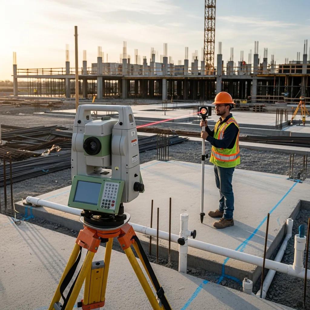
We combine model-driven workflows with field-grade technologies to convert BIM geometry into accurate layout and verified as‑built records—improving installation accuracy and predictability. Key tools include robotic total stations for layout transfer, 3D laser scanners for existing‑conditions capture, and interoperable BIM platforms for model aggregation and clash management. These tools work together: scans produce point clouds for accurate as‑built models; federated BIMs reveal clashes and coordinate trades; and total stations transfer model coordinates to the field for anchor bolt and equipment set-outs. The table below compares these technologies by function and field impact to help project teams weigh trade‑offs.
The technology comparison highlights each tool’s role and the accuracy gains it delivers on site.
| Technology | Key Function | Field Impact / Accuracy Gain |
|---|---|---|
| Trimble Robotic Total Station | Model coordinate transfer and layout control | High‑precision layout, reduced human error for anchors/equipment |
| 3D Laser Scanning | Point‑cloud capture of existing conditions | Accurate as‑built geometry, fewer retrofit surprises |
| BIM Platforms (Revit/Navisworks) | Authoring, aggregation, clash detection | Centralized coordination and validated model exchange |
How the Trimble Robotic Total Station Improves Field Layout Accuracy
A robotic total station transfers model coordinates into the field by establishing control points and guiding precise stake‑out for anchors, hangers, and equipment set‑outs—reducing manual measurement errors. A survey technician can verify installed locations against the BIM with millimeter‑level precision, which matters for prefabricated components that require exact placement. Using a total station speeds layout compared with tape‑and‑level methods and creates a digital record linking physical installation to model elements. For work that needs verified placement—like anchor bolts for mechanical equipment—this technology minimizes rework and streamlines QA/QC.
Integrating layout control with the federated model ensures field‑verified points feed back into the as‑built model, reducing discrepancies at turnover.
How 3D Scanning Supports As‑Built Modeling and Renovation Planning
3D laser scanning captures dense point clouds of existing spaces that we register and convert into as‑built BIM geometry representing current conditions with high fidelity. Scan‑to‑BIM workflows extract model elements from point clouds so designers and modelers can place MEP systems while respecting obstructions and historic features. This reduces surprises during demolition and installation and guides routing and prefabrication decisions in retrofit work. When paired with clash detection, accurate as‑built models let teams evaluate proposed systems against reality and quantify changes early, cutting discretionary field labor and schedule slip.
Quality as‑built BIM supports permit submissions, stakeholder reviews, and fabrication‑ready deliverables for retrofit scopes.
What Is CCLS’s MEP BIM Modeling Process — Concept to Construction?
Our MEP BIM process follows a clear, repeatable path from initial model authoring to fabrication support and as‑built delivery, keeping traceability and constructibility at each stage. Starting from design documents or registered point clouds, models are authored to agreed LOD standards, aggregated into federated models for clash detection, and iterated through coordination cycles. Issues get owners, models are updated and verified, and fabrication detailing and shop drawings are produced when required. Field layout then validates installations and feeds back to the as‑built model. The numbered list below summarizes the typical steps we use to turn design intent into construction‑ready outcomes.
- Model authoring from drawings or point clouds with agreed LOD definitions.
- Federated aggregation and iterative clash detection cycles.
- Coordination meetings to assign and resolve issues.
- Fabrication detailing and shop‑drawing production.
- Field layout verification and as‑built model updates.
Process snapshot: the table below maps core steps to the tools we use and the client outcomes you should expect.
| Process Step | Tools / Inputs | Expected Output / Client Outcome |
|---|---|---|
| Model Authoring | Design drawings, point clouds, Revit | Coordinated discipline models that meet LOD agreements |
| Clash Detection | Federated model, Navisworks | Prioritized clash reports and issue lists |
| Coordination | Meeting cadence, issue tracking | Assigned resolutions and updated models |
| Fabrication Support | Spool detailing, shop drawings | Fabrication‑ready documents and reduced field labor |
| As‑Built Delivery | Field verification, scans | Accurate as‑built BIM for owner operations |
How BIM Models Are Developed and Coordinated Across Trades
Model development starts with clear authoring standards and LOD agreements that define each trade’s responsibilities and expected deliverables. Trades author discipline models in Revit or similar tools and submit them for federation; project leads run clash detection, generate reports, and hold coordination meetings to assign issue ownership. Version control and consistent naming ensure traceability as models are revised and re‑submitted. A coordination cadence—weekly or biweekly depending on schedule—keeps progress moving toward a resolved federated model. Clear upfront standards reduce ambiguity, speed coordination, and support downstream uses such as prefabrication and facility management.
Setting content and quality expectations early saves time and helps models serve construction and operations teams effectively.
Steps in Clash Detection and Multi‑Trade Coordination
Clash detection and coordination follow a disciplined loop: aggregate models, run automated scans, classify and prioritize clashes by severity, assign resolution owners, and verify fixes through re‑runs and sign‑offs. Productive coordination meetings tackle high‑severity items first, set timelines for resolution, and log decisions in an issue tracker that updates the federated model. Categorizing clashes (hard clashes, clearance issues, tolerances) helps teams focus on the right problems and prevents low‑impact items from consuming the schedule. Verification rounds close the loop so resolved clashes don’t reappear in the field and fabrication files reflect the coordinated geometry.
A rigorous clash workflow turns model anomalies into tracked actions and proves reduced field conflicts over successive cycles.
How CCLS Supports Fabrication and As‑Built Documentation
We support fabrication by producing fabrication‑ready models, shop drawings, and spool sheets that specify connection points, cut lists, and hanger locations for off‑site assembly. These deliverables include metadata—materials, sizes, routings—shops use to pre‑cut and assemble components, reducing on‑site labor and install time. After installation, we perform field verification with scanning or layout checks and update the as‑built BIM to reflect actual conditions for owner handover. Accurate as‑built models support long‑term operations, future renovations, and asset management.
Linking model‑driven fabrication with verified as‑built records minimizes punch‑list items and speeds final acceptance and turnover.
How Virtual Design and Construction (VDC) Improves MEP Outcomes in Savannah
VDC extends BIM by using model data within project controls—scheduling, cost, logistics, and quality workflows—to improve sequencing, prefabrication readiness, and predictability. VDC treats BIM as a single source of truth for construction simulation, logistics planning, and digital QA/QC so teams can rehearse installation sequences and spot constructability risks before crews mobilize. On constrained Savannah sites or historic projects, VDC aligns procurement, fabrication, and on‑site activity to reduce disruption and ensure compliance with local conditions. The list below highlights primary VDC benefits for MEP scopes on local jobs.
- Clearer sequencing and installation simulations that cut downtime.
- Better prefabrication planning that shortens field assembly time.
- Tighter integration with cost and schedule controls for predictable results.
VDC creates a feedback loop where field verification updates the model and improves execution on current and future projects.
What VDC Is and Why It Matters for MEP BIM
VDC uses BIM as the foundational data source inside broader project controls—combining models, schedules, cost, and logistics to optimize construction outcomes. Unlike BIM alone, VDC focuses on process integration and decision workflows: running simulations, coordinating sequencing, and preparing prefabrication strategies from model data. For MEP systems, VDC supports assembly sequencing, clash‑aware scheduling, and stakeholder coordination that reduce costly field interventions. Adopting VDC practices improves predictability and fosters collaboration between designers, fabricators, and installers.
Using BIM within a VDC framework produces measurable gains in schedule adherence and installation efficiency.
How CCLS Uses VDC to Streamline Digital Workflows and Construction
CCLS applies VDC by combining model coordination, digital QA/QC, and field integration into a closed‑loop workflow that raises model fidelity and installation readiness. We begin with digital planning—defining LOD, exchange standards, and coordination cadence—then run iterative coordination and verification, followed by field layout and as‑built validation that feeds back into the model. That loop supports prefabrication and reduces on‑site labor by ensuring shop files reflect field realities. By applying VDC methods, we help teams minimize disruption and improve predictability for MEP installations on complex Savannah projects.
The result: less variability in install time and a tighter alignment between model deliverables and field execution.
Common Questions About MEP BIM Modeling Services in Savannah, GA
Project teams commonly ask about software tools, expected Level of Development, delivery timelines, and milestone deliverables. Clear answers set expectations and help with procurement decisions. Below are concise responses to questions decision‑makers often raise when planning MEP BIM services for local projects.
- What software tools are used and for which functions?
- How does LOD affect deliverables and fabrication readiness?
- What coordination cadence and timelines should a project expect?
These practical points help you choose the right BIM scope and align contracts with project goals.
Which Software Tools Support MEP BIM Modeling and Coordination?
Common industry tools include Revit for model authoring and Navisworks for aggregation and clash detection, alongside point‑cloud processing software to register and extract geometry from scans. Revit handles trade‑specific modeling and metadata; Navisworks (or similar aggregators) runs clash detection and timeline simulations; point‑cloud tools convert scans into usable as‑built references. Interoperability through IFC and open exports helps exchange models across platforms and supports fabrication toolchains. Expect deliveries in both native and exportable formats that meet agreed LOD and project requirements.
Choosing the right toolchain affects exchange workflows, revision control, and how easily fabrication teams consume the model data.
How Does Level of Development (LOD) Affect MEP Deliverables?
LOD defines the level of detail and reliability for a model element. Higher LODs (for example, 300–400) move models from design intent toward construction and fabrication readiness by adding accurate geometry and connection detail. At LOD 300, elements represent specific systems for coordination; at LOD 350–400, elements include connection and fabrication specifics suitable for shop drawings. Select the appropriate LOD based on project phase and intended use—decision making, coordination, or direct fabrication—and agree on it early to set deliverable and timeline expectations. Clear LOD definitions limit disputes and ensure models meet installers’ and fabricators’ needs.
Aligning LOD with procurement and shop schedules ensures model outputs are useful in the field and the shop.
If you need a consult or quote, request a consultation with Conway Coordination and Layout Services (CCLS) to define BIM scope, LOD targets, and scan‑to‑BIM needs for Savannah‑area construction and renovation work. We’ll outline deliverables, coordination cadence, and how survey‑grade layout and scanning integrate into your project plan.
Nathan Conway leads CCLS’s coordination consultations and can advise on aligning BIM deliverables with construction sequencing and fabrication requirements.
Frequently Asked Questions
What is the difference between MEP BIM and traditional CAD modeling?
MEP BIM (Building Information Modeling) differs from traditional CAD by creating a 3D, data‑rich model that improves collaboration between disciplines. CAD often focuses on 2D drawings or simple 3D shapes, while BIM embeds system data, enabling clash detection, coordination, and clearer downstream use for procurement and fabrication. In practice, BIM increases accuracy, cuts rework, and streamlines project delivery—especially on complex builds like those we see in Savannah.
How does MEP BIM support sustainability in construction projects?
MEP BIM supports sustainability by reducing material waste and enabling smarter system design. Accurate models produce precise take‑offs, which limit excess orders and overproduction. BIM also allows energy and performance simulations that help choose efficient systems. Taken together, these practices help projects meet sustainability goals and comply with local regulations while lowering lifecycle waste.
What are common challenges when implementing MEP BIM on a project?
Challenges include resistance to change from traditional workflows, the need for specialized training, and integrating multiple software platforms. Aligning stakeholders on standards and expectations can be difficult in multi‑discipline teams. Strong communication, upfront standards, and investment in training and clear protocols make BIM adoption smoother and more effective.
How does MEP BIM improve communication among project stakeholders?
MEP BIM centralizes project information so all stakeholders access the same, current data. This transparency supports better collaboration: teams visualize systems in 3D and understand how changes affect others. Regular coordination meetings and shared models facilitate focused discussions, reduce misunderstandings, and streamline execution.
What role does training play in adopting MEP BIM successfully?
Training is essential. It gives team members the skills to use the tools and workflows effectively, builds confidence, and fosters a collaborative culture. Ongoing training keeps teams current with software and process improvements, maximizing BIM’s benefits across the project lifecycle.
How does CCLS ensure quality control for MEP BIM deliverables?
CCLS enforces quality through iterative clash detection, regular coordination, and adherence to agreed LOD standards. We conduct staged reviews at each modeling milestone and use 3D scanning and robotic total stations for precise field verification. These checks ensure final deliverables meet project specifications and support a smooth handover to owners and facility teams.
Conclusion
MEP BIM modeling in Savannah delivers measurable benefits: less rework, more predictable costs, and smoother coordination between trades. For local contractors, engineers, and owners dealing with renovations or historic constraints, BIM and VDC practices reduce risk and support prefabrication and fabrication‑ready outcomes. To explore how CCLS can improve your next project with practical BIM solutions and precise field layout, contact us for a consultation. Let’s turn model accuracy into on‑site certainty.