Proactive Hazard Identification and Mitigation in Construction: Practical Safety Planning and Risk Management
Proactive hazard identification intentionally finds, analyzes, and addresses site risks before crews arrive—using digital models and precision field layout to cut incidents and avoid costly rework. By combining early design review, virtual simulation, and on‑site verification, hazards are exposed in a controlled setting and resolved through design or sequencing changes. This article explains how proactive work differs from reactive responses, how Virtual Design & Construction (VDC) and Building Information Modeling (BIM) strengthen safety planning, and how precision instruments like robotic total stations and 3D scanning close the model‑to‑field loop. We provide a stepwise safety‑plan framework—model-based hazard simulation, constructability reviews, job hazard analysis, and site verification—plus practical lists, comparison tables, and checklists to help safety managers, BIM coordinators, and project leads turn detection into durable mitigation while improving schedule reliability and cost predictability.
What is Proactive Hazard Identification and Why is it Crucial in Construction?
Proactive hazard identification means finding potential safety risks during pre‑construction and early design so design choices, sequencing, and controls remove or reduce hazards before fieldwork starts. The approach depends on data‑rich models, coordinated multidisciplinary reviews, and scenario testing to reveal clashes, access issues, and temporary‑works needs. The primary payoff is fewer incidents, less rework, and more predictable schedules. This contrasts with reactive approaches that respond after an event—incurring higher costs and disruption. Proactive programs create a feedback loop: model findings inform permit scopes, JHAs, and daily briefings so crews act on prioritized controls. The next section shows how early detection prevents accidents by enabling concrete design and sequencing interventions that remove hazards at the source.
Proactive hazard programs typically deliver three core benefits:
- Improved schedule reliability through fewer field reworks and coordinated sequencing.
- Lower incident rates by resolving design and access hazards before construction.
- Cost avoidance from eliminated clashes and reduced corrective scope.
Those outcomes show why teams should invest earlier in hazard discovery and mitigation instead of absorbing higher downstream costs and safety exposures.
How Does Early Hazard Detection Prevent Construction Site Accidents?
Early detection prevents accidents by exposing causal chains—design conflict → constrained access → improvised workarounds—and removing root causes through design or procedural changes. When simulations reveal fall openings or poor egress during a virtual walkthrough, teams can adjust edge protection, reroute staging, or reschedule tasks to avoid exposing crews during high‑risk activities. The path from detection to prevention includes identification, assignment of mitigations, model verification, and field validation during layout and installation. Tracking near‑misses, corrective actions, and rework hours demonstrates how early detection lowers incident frequency and improves crew behavior. Effective detection converts abstract risks into prioritized, verifiable tasks crews can implement safely.
What Are the Common Types of Construction Hazards to Identify?
Construction projects consistently present hazard categories that should be included in proactive reviews: falls from height, struck‑by incidents, caught‑in/between exposures, electrical risks, environmental hazards, and ergonomic/manual‑handling stresses. Each hazard class shows up differently across phases—design choices may create fall exposures during shell work, while staging decisions can create struck‑by risks during heavy lifts. Proactive measures map to these categories—design‑for‑safety fixes, sequencing changes, exclusion zones, temporary works, and focused training—so mitigations are applied before crews adopt unsafe workarounds. Prioritizing these categories in early reviews ensures high‑consequence hazards are remediated during project development.
How Does Virtual Design and Construction Enhance Construction Safety?
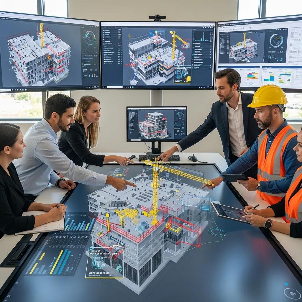
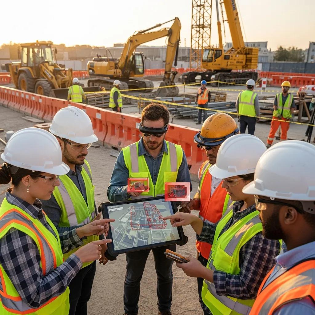
Virtual Design and Construction (VDC) improves safety by using coordinated digital models and process simulations to expose hazards, optimize logistics, and validate sequencing before fieldwork begins. VDC integrates multidisciplinary models, runs scenario simulations, and organizes stakeholder reviews so abstract risks become actionable mitigations. The result is fewer on‑site conflicts and clearer execution plans. With VDC, safety teams run virtual walkthroughs, simulate lifts, and stress‑test access routes so hazardous conditions are either designed out or controlled with temporary works. Feeding VDC outputs into daily planning and JHAs closes the loop between office coordination and field behavior, improving traceability and risk communication.
VDC delivers safety improvements through three principal workflows:
- Hazard simulation and risk visualization to identify pinch points and access issues.
- Clash detection and coordination to remove physical conflicts that drive unsafe workarounds.
- Site logistics modeling to reduce exposure during material handling and heavy lifts.
These workflows convert model intelligence into project controls. The table below summarizes key VDC capabilities and their expected safety outcomes.
Different VDC capabilities map to distinct safety outcomes:
| VDC Capability | Core Attribute | Direct Safety Outcome |
|---|---|---|
| Hazard simulation | Scenario‑based model runs | Identifies pinch points and fall hazards before construction |
| Clash detection | Automated geometry checks | Eliminates installation conflicts that cause rework and unsafe fixes |
| Site logistics modeling | Sequence and layout planning | Reduces material handling exposures and equipment interference |
This table clarifies how each VDC function targets a measurable safety outcome and helps teams prioritize coordination work.
CCLS approach to VDC Consulting: CCLS turns model findings into field‑ready mitigations through a repeatable process:
- Develop integrated digital models and align disciplines.
- Run automated and manual clash detection with safety tagging.
- Align field layout and verify with precision layout tools.
- Monitor performance and iterate across construction phases.
That client‑focused workflow converts detection into verifiable controls while improving constructability and safety visibility for stakeholders.
In What Ways Does VDC Enable Hazard Simulation and Risk Visualization?
VDC enables hazard simulation by aggregating discipline models into time‑sequenced scenarios that test access, temporary works, and high‑consequence activities under realistic constraints. The method begins with model aggregation, continues with sequence‑based simulation, and finishes with stakeholder reviews that select and assign mitigations. Tangible outcomes include adjusted designs, revised schedules, and documented controls. Visual artifacts—animated walkthroughs and annotated screenshots—make hazards explicit for trades and safety teams, helping build consensus on safe work approaches. Simulation shortens the path from identification to mitigation by providing a shared, evidence‑based view of risk.
How Does Clash Detection Through VDC Prevent On-Site Conflicts and Hazards?
Clash detection prevents on‑site conflicts by finding spatial and schedule interferences—such as MEP penetrations through structural elements—that would otherwise force last‑minute fixes and create hazardous workarounds. Typical cycles include automated clash reports, prioritized coordination sessions, and resolved model updates validated for constructability. This reduces the chance trades improvise unsafe installs in tight spaces. Common clash types—MEP routing conflicts, temporary works interference, and equipment access obstructions—can generate struck‑by, caught‑in, or fall exposures in the field. Resolving clashes ahead of installation reduces rework, shortens approvals, and lowers incident risk from hurried corrections.
What Role Does Building Information Modeling Play in Hazard Prevention?
Building Information Modeling (BIM) is the project’s data backbone—storing geometry, metadata, safety tags, sequences, and deliverables that enable design‑for‑safety decisions and constructability reviews. BIM embeds safety‑relevant attributes into model elements so teams can query, schedule, and visualize risks alongside technical information. The main benefit is traceable, model‑driven safety planning that feeds site protocols and daily briefings. When BIM carries safety data, safety officers and coordinators have a single source of truth for permits, temporary works, and on‑site controls, reducing ambiguity during execution. The table below maps BIM elements to direct safety benefits for practical application.
BIM elements linked to safety improvements:
| BIM Element | Attribute | Safety Benefit |
|---|---|---|
| Model geometry | Spatial accuracy | Identifies physical conflicts that create hazards |
| Safety tags | Permit and training metadata | Enables filtering for required PPE and permits by zone |
| Sequencing data | 4D schedule links | Aligns safety controls with construction phases |
The table shows how BIM attributes become operational safety tools—not static files—improving visibility and accountability on projects.
How Does BIM Facilitate Design for Safety and Constructability Reviews?
BIM supports design‑for‑safety reviews by letting multidisciplinary teams run coordinated walkthroughs that include temporary works, access solutions, and erection sequencing, and then capture action items directly in the model for traceable follow‑up. Typical review cycles involve designers, BIM coordinators, safety officers, and trade leads who assess constructability and propose interventions—guardrail locations, temporary platforms, or adjusted lifts. Deliverables include updated model elements, safety‑tagged issues, and revised sequencing exported to permit packages and JHA templates. Centralizing findings in the BIM environment ensures safety interventions persist through procurement and field execution rather than getting lost in emails or meeting notes.
How Can BIM Integrate Safety Data to Improve Site Risk Management?
BIM improves site risk management by embedding safety metadata—training status, permit requirements, isolation points, and hazard tags—into elements so dashboards and daily briefs can filter work packages by risk level and control status. Integration workflows often link model queries with safety management systems and mobile briefings, allowing crews to see localized hazards and compliance checks at the point of work. This creates explicit relationships—e.g., “Equipment requires isolation tag”—that feed automated alerts and checklist generation for supervisors. The result is better traceability, faster corrective action, and measurable improvements in compliance and hazard visibility during execution.
How Do Robotic Total Stations and 3D Scanning Improve Site Safety and Accuracy?
Robotic total stations and 3D scanning improve safety and accuracy by reducing human layout errors, speeding verification, and delivering precise as‑built data that reveal deviations that could become hazards if left unchecked. These methods combine centimeter‑level layout precision from robotic instruments with dense point‑cloud captures that expose encroachments, misalignment, and temporary conditions. The benefit is fewer unsafe reworks and faster validation of critical installations. These technologies tighten the verification loop between model and field, enabling teams to verify tolerance conditions and enforce safety‑critical installs like anchor bolts and equipment bases. The table below contrasts traditional survey methods with robotic total stations and 3D scanning to guide decisions.
Comparing layout and scanning approaches:
| Approach | Accuracy | Time-to-Verify | Safety Impact |
|---|---|---|---|
| Traditional survey | Moderate (cm level) | Slower | Higher rework risk |
| Robotic total station | High (mm–cm level) | Faster | Reduces installation errors |
| 3D scanning (LiDAR) | High (dense capture) | Rapid bulk verification | Detects encroachments and evolving hazards |
This comparison shows how modern layout and scanning methods materially reduce safety exposure from misalignment and undocumented site conditions.
CCLS applies precision layout workflows that combine Trimble robotic total stations with 3D scanning to link model coordinates to physical anchors and equipment. Our approach emphasizes model‑driven control positions and iterative field verification to confirm safe execution of critical installations. Projects using these workflows benefit from fewer installation conflicts and clearer audit trails. Teams planning verification strategies should refer to proven precision layout protocols and as‑built capture cadences to bridge the model‑to‑field gap efficiently.
What Are the Benefits of Precision Layout in Mitigating Installation Errors?
Precision layout reduces installation errors by placing control points and benchmarks from coordinated models so anchor bolts, equipment pads, and routing paths align to design tolerances on first install. This prevents hazardous rework—moving heavy equipment after a foundation pour or cutting penetrations under pressure—that increases incident risk. QA workflows typically include pre‑install checks, as‑built capture with a robotic total station, and discrepancy reports tied back to BIM for corrective action. These steps limit field improvisation and align trades to the intended design. The net effect is better installation accuracy, fewer unplanned hot works, and improved site safety through predictability.
How Does 3D Scanning Support As-Built Verification and Hazard Monitoring?
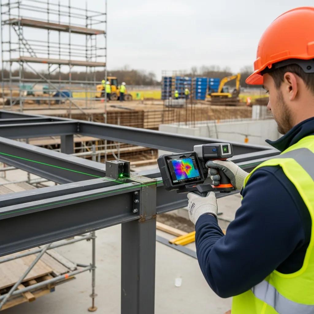
3D scanning supports as‑built verification and hazard monitoring by producing dense point‑cloud snapshots that teams compare to the model to find deviations, encroachments, or evolving conditions that may introduce risk. Planned scanning cadences—pre‑install, mid‑install, and post‑install—yield deviation reports and heatmaps that highlight areas needing attention, enabling mitigation before crews perform hazardous remedial work. Point‑cloud comparisons also document temporary works and access constraints, supplying evidence for safety briefings and verification checklists. Using scans as part of a monitoring program lets teams track high‑risk zones over time and trigger interventions when tolerances or clearances erode.
How to Develop a Comprehensive Construction Safety Plan for Effective Risk Mitigation?
A comprehensive safety plan blends phased risk assessment, integrated digital outputs, and on‑site verification into a single executable framework that guides teams from pre‑construction through closeout. The cycle is: identify hazards in design, document mitigations in the model, schedule controls into sequences, and verify implementation with layout and scan data. The result is repeatable risk control and better compliance. Key components include site and design reviews, JHA creation tied to model elements, permit and training tracking, and daily briefings that reference model‑originated mitigation tasks. The numbered steps below give a practical sequence for building that plan.
- Conduct a pre‑construction review that aggregates models and flags high‑consequence hazards.
- Perform a Job Hazard Analysis that maps risks to tasks and assigns mitigations.
- Integrate mitigations into BIM/VDC deliverables and link them to sequencing.
- Implement field verification with precision layout and scheduled 3D scans.
- Maintain monitoring and continuous improvement cycles based on incidents and near‑miss data.
What Are the Key Steps in Construction Hazard Analysis and Risk Assessment?
Begin hazard analysis with a site and design review to identify exposures, then run a JHA that scores and prioritizes risks for mitigation. Assign owners for each mitigation—design team for design fixes, general contractor for temporary works, safety officer for training and PPE enforcement—so responsibilities are clear. Use consequence and likelihood scoring to focus resources on high‑consequence items and validate chosen mitigations in the model and with field verification plans. Finish with documented acceptance criteria and monitoring triggers that feed daily briefings and permit conditions.
Which Preventative Safety Measures and Protocols Should Be Included?
Preventative protocols should include temporary works design, fall protection systems, exclusion zones for heavy lifts, permit‑to‑work procedures, and targeted training for high‑risk tasks—each backed by model evidence and verification steps. Digital tools support these measures by attaching safety tags to model elements, producing lift plans from simulated sequences, and generating verification checklists for field crews. For example, a temporary platform specified in the model should have an installation checklist and a scan verification before use. Layering engineering, administrative controls, and verification creates a robust prevention system.
Common preventative measures and their digital evidence:
- Temporary works design verified in BIM with manufacturer data attached.
- Fall protection plans linked to model coordinates and installation checklists.
- Exclusion zones documented in VDC logistics models and enforced during lifts.
What Are Real-World Examples of Successful Hazard Mitigation by CCLS?
CCLS has applied integrated VDC, BIM, and precision layout workflows where hazard identification and mitigation were mission‑critical—delivering measurable safety and schedule outcomes through coordinated interventions. Our teams use model‑driven clash detection to prevent equipment collisions, simulate sequencing to lower fall exposures, and validate installations with robotic total stations and 3D scanning to avoid rework that would expose crews to hazards. These case narratives show how pairing early detection with field verification reduces incidents, clarifies responsibility, and improves schedule certainty. For teams seeking a practical partner, CCLS consults to align model‑based hazard detection with on‑site verification protocols.
The following case summaries illustrate typical outcomes and lessons learned:
- VDC‑led fall‑hazard reduction: Simulated access routes led to redesigned temporary platforms and sequencing, removing high‑risk workarounds and sustaining safer access for crews.
- BIM coordination preventing collisions: Multidisciplinary clash cycles revealed equipment and conduit conflicts, enabling prefabrication and routing changes that reduced on‑site maneuvering and exposure during heavy lifts.
- Precision layout validation: Robotic total station layout and follow‑up scanning achieved first‑pass accuracy for critical bases, cutting corrective hot works and associated risks.
These examples show how coordinated digital and field workflows close safety gaps and produce measurable improvements in site risk profiles.
How Did VDC Consulting Reduce Fall Hazards in Project X?
On Project X, VDC consulting simulated façade sequencing and temporary works, uncovering multiple fall‑risk scenarios caused by sequencing overlaps and limited access. The process exposed pinch points early and prompted design changes to temporary platforms, revised access routes, and a staged erection plan that separated high‑risk tasks by time and location. Designers, safety officers, and trade leads reviewed the simulations and approved mitigations that were documented in JHAs and implemented on site. The result: a clearer execution plan with fewer workarounds and a measurable reduction in high‑risk exposures during façade installation.
In What Ways Did BIM Coordination Prevent Equipment Collisions in Project Y?
On Project Y, BIM coordination cycles uncovered clashes between mechanical runs and equipment swing spaces that would have forced last‑minute rework during installation. Through prioritized clash resolution and sequencing adjustments, teams created prefabricated modules and rerouted systems to preserve crane and equipment clearances. These changes removed several on‑site conflict points, reduced corrective welding and cutting, and limited personnel exposure during heavy lifts. The coordination process produced auditable records of resolved clashes and sequencing updates that safety managers used to revise lift plans and exclusion zones.
CCLS invites project teams to request a safety consultation to map model‑driven hazard identification to on‑site verification protocols and to discuss portfolio examples with a project lead such as Nathan Conway. Our consultative approach focuses on turning identified hazards into verifiable controls that improve safety outcomes and project predictability.
Frequently Asked Questions
What tools are essential for proactive hazard identification in construction?
Essential tools include Building Information Modeling (BIM), Virtual Design & Construction (VDC), and precision layout technologies like robotic total stations and 3D scanning. BIM offers a data‑rich environment for visualizing risks, VDC enables scenario simulations to surface hazards before construction, and precision layout ensures accurate installations—together forming a comprehensive framework for identifying and mitigating hazards.
How can teams ensure effective communication of safety protocols on-site?
Ensure effective communication through regular safety briefings, clear signage, and digital tools that integrate safety data into daily workflows. Hold daily huddles to discuss specific hazards and mitigations, referencing model insights from BIM and VDC. Use mobile apps for real‑time updates and checklists to improve crew awareness and compliance. Consistent, visible communication builds a culture of safety and accountability on site.
What role does training play in proactive hazard mitigation?
Training is essential: it equips workers to recognize hazards and follow mitigations. Regular sessions should cover safety equipment, hazard recognition, and emergency response, with hands‑on simulations and scenario‑based drills to reinforce learning. Ongoing training keeps crews current on protocols and technologies, reducing incident rates and strengthening on‑site safety practices.
How can data from past incidents improve future hazard identification?
Past incident data helps by revealing common failure points and systemic risk factors. Analyze incident reports, near‑misses, and corrective actions to identify patterns that inform risk assessments and prioritize high‑consequence hazards in planning. Learning from history lets teams implement more effective mitigations and improve safety on future projects.
What are the benefits of integrating safety measures into the design phase?
Embedding safety into design prevents hazards before construction starts, reducing costly rework and on‑site incidents. Early integration creates more efficient workflows, improves regulatory compliance, and enhances project outcomes. It also fosters collaboration among stakeholders so safety becomes a shared priority throughout the project lifecycle.
How does continuous monitoring contribute to construction site safety?
Continuous monitoring provides near‑real‑time data on site conditions, worker behavior, and protocol compliance. Technologies like 3D scanning and wearables track changes and alert teams to emerging hazards, enabling immediate corrective action. Monitoring reinforces accountability and encourages vigilance, supporting a safer work environment over the life of the project.
Conclusion
Proactive hazard identification and mitigation make construction projects safer, more predictable, and more cost‑effective. Leveraging BIM, VDC, precision layout, and scanning lets teams visualize risk, validate controls, and verify execution before incidents occur. If you want to integrate these practices on your next project, our consulting services can help you build model‑driven safety programs that deliver measurable results.