Anchor Bolt Verification in Greenville, SC — Precision Layout for Reliable Structures
Anchor bolt verification confirms installed anchors match the engineered locations, orientations, and elevations so structural connections fit and assemblies perform as intended. That verification prevents costly rework and erection delays, keeps projects code-compliant, and preserves structural integrity. In this guide we explain why verification matters for Greenville projects, how a disciplined field workflow operates, which technologies improve accuracy, who benefits most, and how QA and compliance are documented. We also show practical examples using tools like robotic total stations, BIM coordination, and 3D scanning, and outline what project teams should provide to speed scheduling and technical review.
Why Anchor Bolt Verification Matters on Greenville Projects
Anchor bolt verification is the on-site check that anchors meet engineered coordinates, tolerances, and orientation so they can transfer loads and fit connections correctly. Accurate verification reduces structural risk, limits rework, and protects the schedule by catching deviations before steel erection or equipment installation. On Greenville jobs, early verification prevents situations where base plates cannot be shimmed or fabricated connections must be altered—scenarios that create downtime and extra fabrication. The section below explains how placement accuracy affects stability and load paths.
Anchor bolt verification delivers three core benefits for Greenville projects:
- Safety assurance: Verifies anchors will transfer loads as designed and helps prevent connection failures.
- Cost avoidance: Finds deviations early to avoid rework, fabrication changes, and schedule impacts.
- Compliance: Produces the documentation owners and inspectors require for acceptance and special inspections.
These advantages show why pre-pour and pre-erection verification are built into disciplined layout workflows and lead to more predictable outcomes.
How Accurate Anchor Bolt Placement Affects Structural Stability
Anchor placement controls load paths, connection fit-up, and the ability of base plates and anchors to carry shear and tension as designed. When bolts are placed within millimeter-level tolerances relative to base plates, connections align, grout and weld interfaces perform, and members resist applied forces according to the engineer’s assumptions. Tight-tolerance projects—industrial or healthcare—often require only a few millimeters of deviation; larger structural elements may accept somewhat broader ranges set by the engineer of record. Knowing those thresholds helps teams set verification frequency and plan remedial work when needed.
Risks and Costs of Misaligned Anchor Bolts
Misplaced anchor bolts trigger direct costs—fabrication rework, extra labor, or anchor replacement—and indirect costs such as schedule extensions, crane downtime, and contractual disputes. Rework frequently consumes a disproportionate share of unexpected project expenses and can ripple into erection sequencing and equipment installation. Safety also suffers when connections are forced to fit or field-built shims exceed approved limits, potentially undermining design assumptions. The list below summarizes common impacts to help teams evaluate remediation options.
- Fabrication changes: Reworking prefabricated members to match field conditions adds time and cost.
- Schedule delays: Erection and following trades stall when anchors are out of tolerance.
- Increased risk: Improvised fixes can introduce safety and performance problems.
Because of these consequences, precise, early verification is a core risk-management practice on complex projects.
Our Anchor Bolt Verification Process at CCLS
Our process ties digital plan intake to precise field layout with a Trimble Robotic Total Station (RTS) and to clear as-built documentation that confirms compliance with engineered coordinates and tolerances. Conway Coordination and Layout Services (CCLS), a family-owned firm serving the Southeast, begins with BIM/CAD import and datum checks, moves to RTS-based layout and measurement, and finishes with deviation reporting and remediation coordination. This structured workflow reduces coordinate-conversion errors, aligns field crews and fabricators, and produces traceable records for special inspections. The paragraphs below describe key steps, expected tolerances, and how deliverables support contractor and engineer decisions.
The table below summarizes verification phases, typical tolerances, and the deliverables stakeholders receive.
| Verification Phase | Typical Tolerance | Deliverable |
|---|---|---|
| Digital Plan Integration | ±2–5 mm (model-to-control) | Validated model references and coordinate report |
| RTS Field Layout | ±1–3 mm (final set positions) | Field coordinate logs and stakeout confirmation |
| As-Built Documentation | ±2–5 mm (measured vs. designed) | Deviation table, annotated drawings, photos |
This table sets expectations for precision at each stage and identifies the practical outputs teams use to accept or remediate work. The following section explains how digital plan integration reduces errors before crews mobilize.
How Digital Plan Integration Improves Accuracy
Digital plan integration creates a single source of truth by importing BIM or CAD models into the layout control environment and ensuring coordinates, datums, and model geometry align with site control. Early verification of the coordinate system and datum prevents unit or reference mismatches that produce systematic offsets in anchor locations. Integration also supports clash detection and early communication with fabricators when embeds conflict with other trades, reducing surprises during erection. Use this checklist before mobilizing: confirm the coordinate system, verify control monuments, and run a model-to-field spot check.
- Checklist: Confirm coordinate system, verify control monuments, perform model-to-field spot checks.
These pre-field checks set the RTS workflow up for success and reduce repeat site visits.
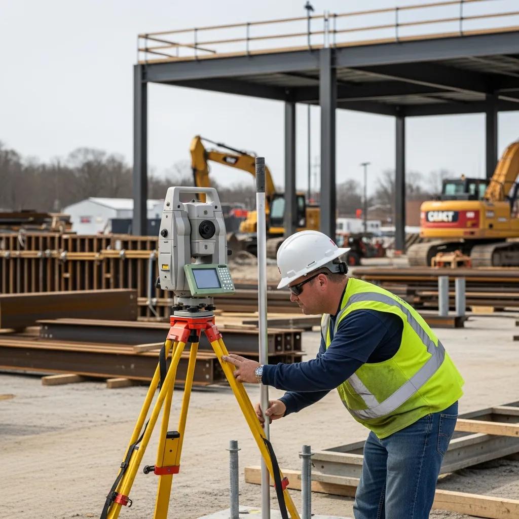
Using a Trimble Robotic Total Station for Precise Layout
A Trimble Robotic Total Station delivers millimeter-level accuracy and automated stakeout, enabling teams to place anchors and record as-built coordinates efficiently. RTS setup begins by establishing control points tied to the project datum, then uses robotic positioning to stake target anchor locations from the integrated model. Each measured anchor position and orientation is logged, producing a verifiable dataset to compare against the design model and to generate deviation reports and annotated as-built drawings. RTS reduces human error compared with tape-and-transit methods and provides the traceable records engineers need for acceptance.
Data recorded by the RTS feeds reporting workflows that document variances and recommend remediation, preparing the team for acceptance or corrective action.
How Advanced Technology Improves Verification
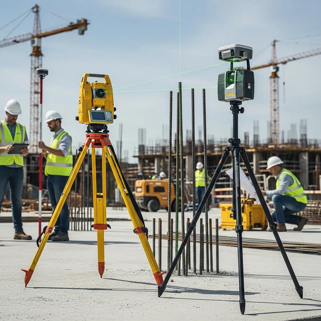
Advanced tools—Trimble RTS, BIM/VDC coordination, and 3D scanning—tighten tolerances, speed data exchange, and enable model-to-field comparisons that catch errors earlier. RTS provides precise layout and measurement, BIM/VDC supports coordination and clash resolution, and 3D scanning captures dense as-built data for deviation analysis. When combined (BIM → RTS → 3D scan) these technologies reduce RFIs, accelerate erection, and produce defensible QA/QC records for owners and inspectors. The table below compares each tool by accuracy and typical use case.
| Technology | Accuracy | Typical Use Case |
|---|---|---|
| Trimble RTS | ±1–3 mm | Final anchor stakeout and measurement |
| BIM / VDC | Model accuracy dependent | Coordination, clash detection, fabrication guidance |
| 3D Scanning (LiDAR) | ±5–10 mm (scan) | As-built capture and model-to-scan deviation reports |
This comparison helps project teams choose the right mix of tools for accuracy and documentation needs. Below we describe how CCLS applies these technologies in practice.
At CCLS we validate models in the office, deploy RTS teams for precise stakeout and measurement in the field, and use 3D scanning selectively for complex or high-tolerance installations. That practical integration turns theoretical advantages into measurable reductions in rework and faster acceptance by engineers and inspectors.
The Role of BIM and VDC in Anchor Bolt Coordination
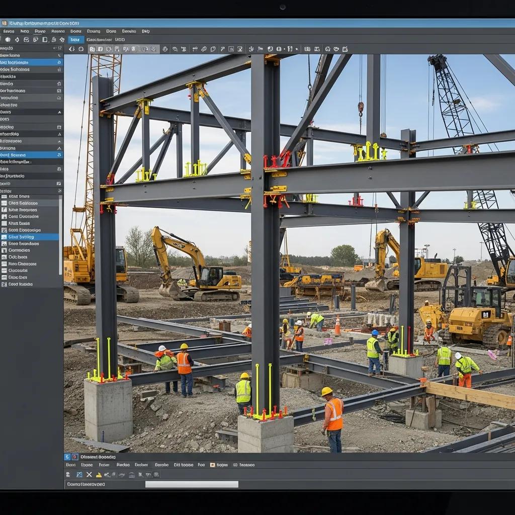
BIM and VDC create a coordinated digital model that exposes clashes, dimensional conflicts, and sequencing issues before crews arrive. Model-based references give contractors and fabricators exact anchor locations and orientation details, improving fit-up and reducing onsite adjustments. Typical VDC deliverables include clash reports, annotated model views, and updated anchor schedules that feed directly into RTS stakeout files. These outputs streamline communication between engineers, fabricators, and layout crews and reduce field surprises.
How 3D Scanning Supports As‑Built Verification
3D scanning captures dense point clouds of installed anchors and surrounding structure to produce a precise as-built record registered to project control. Automated comparisons between the point cloud and the design model highlight offsets and tilt, and generate quantified deviation tables and visual heat maps for stakeholders. Scans are especially valuable on tight-tolerance industrial and healthcare installs where small misalignments can affect equipment fit or process performance. After scanning, teams deliver actionable reports that indicate whether anchors are within tolerance or require remediation, guiding final acceptance or corrective workflows.
Who Benefits from Anchor Bolt Verification Services in Greenville, SC?
Anchor bolt verification helps a wide set of stakeholders—general contractors, structural engineers, fabricators, erectors, and owners of industrial or healthcare facilities—where connection accuracy is critical for safety, performance, and uptime. General contractors gain schedule predictability and fewer change orders; engineers receive verifiable data that confirms design assumptions; fabricators and erectors see fewer fit-up issues; and owners protect expensive equipment installations and regulatory compliance. The sections below describe the firms that typically rely on verification and why certain sectors demand millimeter-level precision.
Teams that rely on verification commonly include general contractors, structural engineers, surveying and layout subcontractors, and trade contractors responsible for steel erection and equipment installation. Verification is coordinated at key milestones—pre-pour embed setting, pre-erection checks, and final as-built validation before equipment turnover. Embedding verification into contract milestones reduces disputes about responsibility and clarifies acceptance criteria, helping keep the project on schedule.
Which Construction and Engineering Firms Rely on These Services?
General contractors and structural engineers use anchor bolt verification to confirm field conditions match engineered assumptions before committing to erection or equipment installation. Surveying and layout subcontractors provide measurement and stakeout expertise, while fabricators and erectors use verification outputs to plan fit-up and sequencing. Project managers schedule verification at pre-pour and pre-erection gates to establish clear acceptance points and to reduce late-stage changes that disrupt procurement. Clear roles and deliverables among these parties simplify remediation when deviations occur.
Why Industrial and Healthcare Projects Prioritize Precision
Industrial and healthcare facilities demand strict tolerances because anchored equipment, process lines, and cleanroom interfaces require precise alignment to function and meet regulatory standards. Misalignment in pharmaceutical or medical equipment foundations can cause validation failures, downtime, and costly recalibration; manufacturing installations often require vibration and settlement tolerances that depend on accurate anchor placement. The combination of high equipment value, regulatory oversight, and uptime requirements makes measurement-led verification and documentation essential. Proper reports then support inspections, commissioning, and long-term reliability.
- List of sector drivers:
- Equipment alignment needs: Precise anchors keep machinery within design tolerances.
- Regulatory scrutiny: Healthcare and pharma projects require thorough documentation for validation.
- Operational uptime: Accurate installation reduces commissioning risk and downtime.
These drivers explain why owners and engineers often require measurement-based verification as acceptance criteria.
How CCLS Ensures Compliance and Quality
CCLS follows quality workflows that map code and inspection requirements to measurable deliverables—validated as-built drawings, deviation tables, and photographic evidence—to support special inspections and engineer acceptance. Our documented method ties model validation, control verification, and measurement reporting to inspector expectations. That approach yields traceable documentation for IBC-related special inspections and coordinates remedial actions when deviations exceed allowable tolerances. The table below links common inspection triggers to the deliverables we provide.
| Code / Inspection Trigger | Required Deliverable | CCLS Method |
|---|---|---|
| IBC special inspection trigger | As-built position report and photos | Model validation, RTS measurement, deviation table |
| Anchor tension/installation check | Installation record and corrective actions | Field verification logs and remediation coordination |
| Pre-erection acceptance | Annotated layout drawings | Final stakeout confirmation and signed deliverables |
This mapping clarifies how inspection triggers translate into tangible outputs that satisfy engineers and inspectors; the following sections describe typical report contents and formats.
What Building Codes and Special Inspections Are Addressed?
Anchor bolt verification supports building-code frameworks that require special inspections for certain anchor applications and critical connections. Typical triggers include seismic or wind-resisting elements, heavy-equipment foundations, and other critical structural connections where inspectors ask for documentation showing anchors were placed per the engineer’s drawings. CCLS prepares measurement reports and annotated drawings that align with inspector expectations and can coordinate additional tests or proof-load checks if the engineer of record requires them. Delivering these reports early simplifies special inspection sign-offs and moves projects toward final acceptance.
How We Deliver Detailed Reports and Documentation
CCLS verification reports include position tables that compare installed coordinates against design coordinates, annotated plan views, photos of embedded conditions, and recommended remediation when deviations exceed tolerance. Deliverables commonly come as PDF reports for distribution, CAD/BIM updates to reflect as-built positions, and CSV or coordinate logs for engineer review and archival. These standardized outputs let engineers sign acceptance or specify corrective actions for contractors to complete before final sign-off—reducing ambiguity and speeding inspections and approval.
How to Request Anchor Bolt Verification Services in Greenville, SC
Requesting verification is straightforward: provide project plans and the timeline, allow a scope review to define control and tolerances, and schedule on-site verification to align with critical milestones. CCLS begins with a document review and model validation, then issues a tailored statement of work that defines tolerances, deliverables, and mobilization timing. For Greenville projects, having BIM/CAD files, control coordinates, and planned pour and erection dates on hand speeds quoting and scheduling.
To prepare for engagement, assemble the following items and expect the initial phases described below:
- Project plans and BIM/CAD files: Provide model files for digital plan integration and control checks.
- Project timeline: Share pour dates, erection windows, and critical milestones.
- Control information: Supply known control points or monuments to align site control.
These materials enable a smooth scoping and scheduling process and lead into our three-step consultation flow.
Steps to Schedule a Consultation with CCLS
Scheduling a consultation follows three practical steps: initial contact and document submission, scope review and quote, and scheduling of the verification mobilization.
First, send project plans, BIM/CAD files, and timeline constraints so we can validate model compatibility and estimate control work.
Second, CCLS performs a scope review to define tolerances, equipment needs (RTS, scanner, etc.), and deliverables, then provides a clear quotation and schedule estimate.
Third, after scope approval we coordinate mobilization to align pre-pour embeds or pre-erection checks with your schedule, minimizing disruption to construction sequencing.
These steps reduce lead time between inquiry and field verification and make it easier for project teams to integrate measurement controls into the critical path.
Where to Find Case Studies That Demonstrate Our Work
CCLS maintains a portfolio of verification projects that document methods, challenges, and outcomes—examples where precise layout and documentation prevented rework and sped erection. Portfolio entries typically include a project summary, the technologies used (RTS, BIM, 3D scanning), measured outcomes like deviation statistics, and descriptions of coordination with engineers and fabricators. Prospective clients can request project-specific references or technical write-ups for Greenville and Southeast projects to evaluate methods and expected results for similar scopes.
This guide has covered the reasons, processes, technologies, beneficiaries, compliance mapping, and engagement steps for anchor bolt verification in Greenville—providing a clear path to implement measurement-driven quality assurance on structural projects.
Frequently Asked Questions
What technologies are commonly used in anchor bolt verification?
We commonly use Trimble Robotic Total Stations (RTS) for millimeter-level stakeout and measurement, BIM/VDC for coordination and clash detection, and 3D scanning (LiDAR) for dense as-built capture. RTS handles final stakeout; BIM drives coordination and fabrication guidance; 3D scans validate installs and quantify deviations. Together these tools improve accuracy, reduce rework, and speed acceptance.
How can misalignment of anchor bolts affect project timelines?
Misaligned anchors can halt erection, force rework, and create idle time for cranes and crews—pushing out follow-on trades and extending the schedule. Resolving misalignment often requires extra inspections and adjustments, further delaying progress. Early verification reduces these risks and helps keep the project on track.
What documentation is required for special inspections related to anchor bolts?
Inspectors typically request as-built position reports, installation records, and photographic evidence showing embedded conditions. Deviation tables that compare measured versus design coordinates are often required when anchors are critical. Providing thorough, traceable documentation simplifies inspection sign-off and supports engineer acceptance.
What are the typical tolerances for anchor bolt placement?
Tolerances depend on project type and the engineer of record. High-precision applications—industrial or healthcare—may require ±1–3 mm. Larger structural elements commonly accept ±2–5 mm. Those ranges determine verification frequency and remedial thresholds.
How does anchor bolt verification contribute to safety on construction sites?
Verification confirms anchors meet design requirements, ensuring connections transfer loads as intended and reducing the likelihood of forced fits or unsafe field modifications. By catching issues before erection, verification protects crews and helps maintain the structural performance the design assumes.
Who is responsible for conducting anchor bolt verification?
Specialized surveying and layout subcontractors typically perform anchor bolt verification in coordination with general contractors and structural engineers. Project managers schedule verification at critical milestones—pre-pour and pre-erection checks—to ensure compliance and protect the project schedule.
Conclusion
Anchor bolt verification is a practical, cost-effective way to protect safety, schedule, and compliance on Greenville construction projects. Verifying anchor locations early prevents rework, keeps erection on schedule, and provides the documentation engineers and inspectors require. Contact CCLS to learn how our verification services can reduce risk and keep your next project moving smoothly.