Industrial Facility Layout & Coordination in Durham, NC — Practical, Precision-Driven Solutions for Manufacturing and Construction
Industrial facility layout and coordination determine how equipment, systems, and workflows are positioned so plants run safely and efficiently in Durham, NC. This guide shows how precise layout, model-driven coordination, and field-verified as-built documentation cut rework, shorten schedules, and protect operations during new builds and renovations. You’ll get clear explanations of core topics—what facility layout actually involves, how Robotic Total Stations deliver millimeter-level placement, why BIM coordination stops costly clashes, how VDC sequences work to avoid downtime, and how 3D scanning produces dependable as-builts. We focus on practical strategies for Durham’s industries—advanced manufacturing, life sciences, and data center support in Research Triangle Park—offering tool and workflow recommendations plus outcome examples teams can act on to reduce schedule risk and construction cost overruns.
What is Industrial Facility Layout and Coordination in Durham, NC?
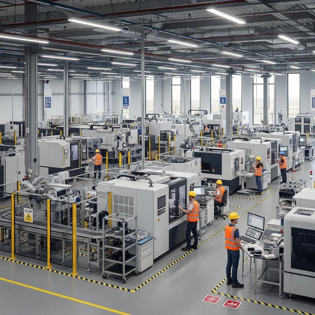
Facility layout and coordination is the process of arranging production equipment, structure, and MEP systems so workflow, safety, and constructability align. It blends spatial planning, sequencing, and model-driven verification to make design intent buildable and to limit clashes and downtime during installation. In Durham projects—where dense MEP routing and heavy machinery share tight footprints—good layout directly supports throughput and regulatory compliance. Below are the primary benefits structured layout and coordination deliver on local projects, helping owners and contractors understand why early investment pays off.
Industrial layout and coordination delivers three core benefits for industrial projects in Durham:
- Increased Operational Efficiency: Smarter material flow, less handling, and intentional equipment spacing boost throughput and shorten cycle times.
- Improved Safety and Compliance: Proper clearances, planned egress, and correct equipment spacing reduce incident risk and help meet OSHA and NFPA requirements.
- Cost and Schedule Control: Early clash detection and field-verified layout cut rework, lower change orders, and prevent schedule slippage.
Those advantages explain why multidisciplinary coordination is central to plant construction and renovation—and why clearly defined roles and workflows matter on Durham sites.
How does facility layout impact industrial efficiency and safety?
Layout determines material flow, worker movement, and maintenance access—factors that combine into overall equipment effectiveness (OEE). Poor layouts increase travel distances, create handling bottlenecks, and produce pinch points that slow production and raise safety risks. Well-planned layouts enable lean workflows and predictable maintenance. For example, locating utilities and spare parts near high-use equipment reduces repair downtime and removes the need for risky, rapid movement of heavy loads. Grasping these operational dynamics points directly to the cross-discipline alignment needed to deliver effective layouts in Durham.
Who plans and manages industrial layouts in Durham's manufacturing sector?
Layout planning and delivery are a team effort: industrial and process engineers, architects, MEP designers, BIM/VDC coordinators, and general contractors translate operational needs into buildable sequences. Owners and plant engineers set performance and safety requirements, BIM coordinators merge models and run clash cycles, and field surveyors and layout techs validate anchor bolts, equipment positions, and hanger locations during installation. Clear role definitions and continuous coordination reduce ambiguity and speed resolution of constructability issues on Durham projects.
Local providers also bridge the gap between model coordination and field execution. Conway Coordination and Layout Services (CCLS) offers Robotic Total Station layout, BIM modeling and coordination, VDC consulting, and 3D scanning to convert coordination outputs into precise field work—especially useful on tight schedules.
How Does Robotic Total Station Layout Enhance Industrial Projects in Durham?
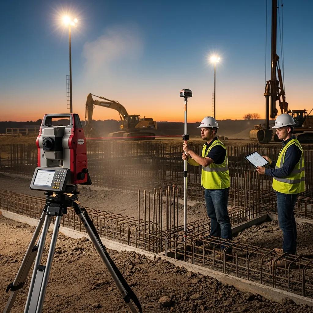
Robotic Total Station layout is a survey-driven, automated positioning workflow that places points in the field with millimeter-level precision by tracking a prism or reflector against a digital model. The technology improves repeatability, reduces manual measurement error, and enables direct field-to-model verification for MEP hangers, anchor bolts, and equipment set points. Robotic Total Stations integrate with BIM and VDC to export coordinate sets for installation and to import as-built verification data back into models. Below is a practical comparison of common layout tasks showing expected accuracy and typical deliverables for industrial work.
The following table compares common layout tasks, expected accuracy, and typical deliverables for Robotic Total Station-driven workflows.
| Task | Typical Accuracy | Common Deliverable |
|---|---|---|
| MEP hanger layout | ±5–10 mm | Field layout points, hanger position list |
| Anchor bolt verification | ±2–5 mm | Anchor as-built report, coordinates CSV |
| Equipment/foundation layout | ±3–10 mm | Anchor bolt layout, equipment set points |
This snapshot shows Robotic Total Stations deliver consistent precision across tasks, and that coordinate exports, CSVs, and verification reports feed directly into model reconciliation and quality control workflows.
What are the key advantages of using Trimble Robotic Total Station for industrial layouts?
Trimble Robotic Total Stations offer four core benefits: high accuracy, faster layout cycles, consistent repeatability between crews, and clean integration with model coordinates. Millimeter-level accuracy reduces field rework and inspection time; robotic tracking speeds multi-point layouts that would otherwise take many labor hours; and repeatability lets following trades rely on prior layout without redundant checks. Those benefits are especially valuable on Durham projects with dense MEP and tight equipment tolerances.
How is robotic total station technology applied in MEP and structural coordination?
Typical robotic layout moves from model export to stakeout to verification and reconciliation: BIM exports coordinates for hangers, penetrations, and anchors; field crews stake the points and install components to those coordinates; then as-built coordinates are captured and compared to the model for clash checks. This closed-loop process catches spatial conflicts before they become costly field changes and supports anchor bolt verification and penetration coordination. VDC ties into this workflow through scheduled layout windows and prefabrication alignment to improve on-site assembly and constructability.
After reviewing workflow applications, teams often compare tasks to decide which benefit most from robotic layout versus conventional methods—an evaluation that naturally transitions into BIM-driven coordination where layout and clash data converge.
Why is BIM Coordination Essential for Manufacturing Plant Layouts in Durham?
BIM coordination brings discipline models together to detect clashes, sequence installations, and produce deliverables that cut on-site errors and rework. By identifying spatial conflicts virtually—between MEP, structure, architecture, and equipment—teams resolve issues before crews mobilize, improving predictability for plant construction. Coordination produces clash reports, updated models, and coordination drawings that guide layout crews. In Durham projects, disciplined BIM workflows also track issue resolution, reduce RFIs, and yield measurable reductions in downstream rework.
The table below maps common BIM tools and coordination outcomes, showing how tool choice links to measurable results.
| Tool/Workflow | Characteristic | Typical Outcome |
|---|---|---|
| Revit + discipline models | Authoritative design models | Coordinated model LOD 300–400 |
| Navisworks clash detection | Aggregated clash reports | Reduced field clashes pre-install |
| Model management (CDE/BCF) | Issue tracking and exchange | Faster resolution and audit trail |
In practice, Revit and Navisworks form the core technical stack for aggregation and clash detection, while model management ensures accountability and a clear audit trail for coordination decisions.
How does BIM coordination prevent clashes and reduce rework in industrial construction?
BIM coordination prevents clashes by aggregating discipline models, running automated clash checks, and resolving issues through coordination cycles before installation. Early detection reveals routing conflicts, clearance violations, and structural interferences so teams can adjust duct runs, pipe risers, or equipment locations in the model rather than in the field. A process that lowers detected clashes by 60–80% across model iterations typically delivers measurable downstream savings in labor and schedule contingency. That reduction in RFIs and change orders directly lowers cost overruns on Durham projects.
Which BIM tools and workflows are used for effective industrial facility coordination?
Effective coordination combines Revit for discipline content, Navisworks for clash aggregation, and structured issue exchange via BCF or a common data environment for traceability. Best practices include disciplined model naming and version control, scheduled coordination sprints aligned to installation phases, and defined LOD targets for coordination deliverables. These steps ensure models are reliable inputs for layout crews and prefabrication packages and create traceable deliverables for governance and handover. CCLS uses these Revit and Navisworks workflows, and recent projects show fewer coordination cycles and faster field turnover for manufacturing retrofits.
What Role Does VDC Consulting Play in Optimizing Industrial Construction in Durham?
VDC (Virtual Design and Construction) consulting extends BIM coordination with schedule modeling, logistics planning, and prefabrication sequencing to improve constructability and reduce schedule risk. VDC delivers 4D simulations that visualize installation sequences, surface site access constraints, and optimize crane and material deliveries for plant construction. When sequencing aligns with prefabrication and just-in-time deliveries, VDC reduces on-site labor congestion and prevents sequencing-related rework. For Durham sites with tight staging, effective VDC can shave weeks off critical-path schedules.
VDC deliverables typically include 4D sequences, prefabrication packages, and logistics plans that coordinate crews, materials, and equipment for predictable outcomes. The highest-impact VDC uses on industrial builds are coordinating prefabricated MEP racks, staging heavy lifts, and sequencing tie-ins to production lines to minimize downtime during cutovers. The next section explains how those deliverables translate into measurable efficiency gains.
How does VDC improve project efficiency and workflow in industrial facility builds?
VDC improves efficiency by simulating construction sequences, exposing site-logistics conflicts, and enabling prefabrication that reduces field labor and install time. For example, sequencing prefabricated pipe racks in a 4D model lets teams validate access, crane lifts, and temporary storage before fabrication starts—cutting coordination conflicts and speeding installation. VDC also produces KPIs—reduced on-site labor hours per installation and fewer change orders—that quantify benefits for owners and contractors and justify early VDC investment on complex Durham projects.
What are best practices for implementing VDC in Durham's industrial projects?
Successful VDC follows a practical checklist: align stakeholders, set data standards, run a pilot sprint on representative scope, and track KPIs to validate outcomes. Key steps include defining LOD expectations, establishing a common data environment, and measuring coordination cycle time and on-site rework hours. Locally, coordinate VDC schedules with permit timelines and labor availability so simulations reflect real constraints. These practices produce repeatable processes that integrate with layout and BIM coordination and lead to better as-built capture and digital handover.
With that checklist in place, precise as-built capture via 3D scanning becomes the foundation for reliable model updates and digital twins.
How Does 3D Scanning Support Accurate As-Built Documentation for Industrial Facilities?

3D laser scanning captures dense point clouds that record existing conditions with high spatial fidelity, enabling accurate as-built documentation for renovations, facility management, and model reconciliation. Point clouds act as a single-source geometric record that lowers measurement uncertainty, informs retrofit decisions, and supports digital twin creation. Scan-to-BIM workflows bring scan data into Revit so coordination models match the field and prefabrication fits as intended. The table below compares common scan deliverables by resolution, accuracy, and typical integration method for industrial use.
| Deliverable | Typical Accuracy | Integration Method |
|---|---|---|
| Raw point cloud (registered) | ±5–10 mm | Import into point cloud viewer / Revit |
| High-resolution scan for critical equipment | ±2–5 mm | Targeted Scan-to-BIM modeling |
| Mobile mapping for logistics | ±10–30 mm | Produce floorplans and clearances |
Targeted high-resolution scans are used where millimeter accuracy matters; broader mobile scans support logistics and space planning.
What are the benefits of 3D laser scanning for renovation and facility management?
3D scanning reduces surprises by delivering accurate spatial records that speed renovation design, procurement, and installation planning—shortening downtime for sensitive industrial systems. Scans support facilities management with precise asset locations, as-built dimensions, and clearance checks that improve maintenance planning and spare-part procurement. For renovations, scans remove the need for repeated field measurements and enable prefabrication with confidence. On Durham projects where downtime and precision matter, scanning is a practical investment.
How is point cloud data integrated into BIM models for industrial coordination?
Point cloud integration follows a Scan-to-BIM workflow: capture and register scans, clean and segment the cloud, then model critical geometry in Revit to the agreed LOD for coordination and fabrication. Quality checks verify registration accuracy, control points, and alignment with project coordinates before modeling. Deliverables usually include Revit families fit to the point cloud, annotated 2D plans, and exportable coordinates for layout tools like Robotic Total Stations. Clear deliverable expectations and validation steps ensure Scan-to-BIM outputs support coordination and precise field layout.
With reliable Scan-to-BIM outputs, teams can select layout strategies that match operational goals and construction realities—leading into the layout optimization strategies below.
What Strategies Optimize Manufacturing Plant Layouts in Durham for Maximum Productivity?
Optimizing plant layouts means choosing the right layout type, mapping material and personnel flows, and validating decisions with field verification and model-driven coordination. Common layout approaches—process, product, cellular, and fixed-position—fit different production models and equipment footprints. Optimization follows workflow analysis, simulation, and staged verification to balance throughput, safety, and maintenance access. The list below summarizes layout types and when to use them, so teams can match strategy to manufacturing needs.
- Process Layout: Ideal for job-shop or variable-product facilities where equipment groups by function and flexibility is essential.
- Product Layout: Best for high-volume, repetitive manufacturing where linear flow and minimized WIP are priorities.
- Cellular Layout: Effective for mixed-model lines where part families are grouped into cells to reduce movement and changeover time.
- Fixed-Position Layout: Appropriate for very large assemblies or heavy installations where the product stays put and trades come to the work.
This typology helps teams pick a layout that supports operational goals and defines the field verification needed to confirm buildability and compliance.
What are the different types of industrial facility layouts and their applications?
Process, product, cellular, and fixed-position layouts address distinct production and space constraints. Process layouts group similar machines for flexibility; product layouts sequence equipment for a single product line; cellular layouts cluster multifunctional cells for families of parts; fixed-position layouts suit large, immobile assemblies. The right choice depends on volume, product mix, and changeover needs, and each layout brings different coordination requirements for MEP, material handling, and egress. Knowing these applications informs how teams proceed with digital verification and field layout.
How does CCLS tailor layout optimization to Durham's industrial sectors?
CCLS combines industry analysis, stakeholder workshops, and field verification—surveying and targeted scanning—to produce practical layout plans for Durham clients. We start by capturing operational requirements, model multiple layout scenarios, then verify fit and clearances in the field with Robotic Total Stations or targeted scans. This integrated approach aligns design intent with real-world constructability so clients see fewer installation surprises and better schedule certainty. For local projects, CCLS positions this service as a direct path from strategy to verified field execution.
When teams want to validate assumptions and turn optimization into measurable installation deliverables, a site-specific assessment is the logical next step.
Frequently Asked Questions
What factors should be considered when selecting an industrial facility layout type?
Choose a layout based on production volume, product variety, and workflow goals. Consider space constraints, equipment footprints, flexibility needs, and safety requirements. Engage stakeholders early—operators, maintenance, and safety personnel—to capture real requirements and make sure the layout serves current operations and future growth.
How can digital tools enhance the accuracy of facility layouts?
Digital tools like BIM and Robotic Total Stations add spatial precision and speed. BIM visualizes complex systems and finds clashes before construction; Robotic Total Stations deliver millimeter-level placement in the field. Together they reduce manual errors, speed coordination, and help installations match the digital model.
What role does stakeholder collaboration play in successful facility layout projects?
Collaboration ensures all perspectives—engineering, operations, maintenance, safety, and construction—are included. Early alignment avoids late changes, speeds decision-making, and reduces risk. Regular coordination cycles and clear accountability keep projects moving and ensure the layout meets operational needs.
What are the common challenges faced during industrial facility layout planning?
Frequent challenges are space limitations, competing operational needs, complex system integration, unexpected site conditions, and regulatory compliance. Clear communication, accurate field data, and the right digital tools (BIM, scanning) help mitigate those risks and keep the project on track.
How does effective facility layout contribute to sustainability in industrial operations?
Effective layout reduces waste and energy use by shortening material movement, improving process flow, and enabling efficient HVAC and lighting strategies. Thinking about lifecycle impacts and designing for reuse and easy maintenance also supports sustainability goals and lowers operating costs over time.
What metrics can be used to evaluate the success of an industrial facility layout?
Measure throughput, cycle time, and equipment utilization for operational performance. Track safety metrics like incident rates and regulatory compliance. Also quantify cost savings from reduced rework and change orders, and measure employee productivity and satisfaction to get a full picture of layout effectiveness.
Conclusion
Precise facility layout and coordination in Durham, NC deliver measurable improvements in efficiency, safety, and cost control for manufacturing and construction projects. By combining BIM, Robotic Total Stations, VDC consulting, and targeted 3D scanning, teams can reduce rework, tighten schedules, and protect operations. Understanding these tools and workflows helps stakeholders make informed choices that align with operational goals. For practical, site-specific solutions to optimize your facility layout, reach out to our team at CCLS—we’ll help turn coordination into predictable field results.