Precise MEP Layout with Robotic Total Stations — Reliable BIM‑to‑Field Execution
Accurate mechanical, electrical, and plumbing (MEP) layout drives schedule certainty and cost control. Robotic Total Station (RTS) systems address the tolerance and coordination gaps that most often cause rework. This article shows how RTS—particularly Trimble Robotic Total Station solutions—delivers millimeter‑level accuracy, repeatable stakeout, and direct BIM‑to‑field workflows. You will learn how RTS works, why it outperforms traditional layout methods, how BIM integration and clash detection reduce conflicts, and which MEP tasks gain the most from RTS. We also outline practical implementation steps for HVAC, plumbing, electrical, and anchor‑bolt verification and describe how an experienced provider executes these workflows on real projects. Along the way we include concise lists, comparison tables, and measured project outcomes so teams can evaluate RTS for prefabrication, VDC coordination, and field verification.
What is Robotic Total Station Technology and How Does It Enhance MEP Layout?
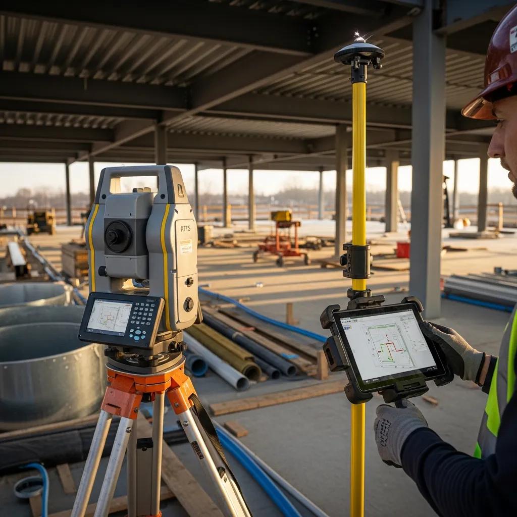
Robotic Total Station technology is an automated surveying instrument that measures angles and distances with optical and electronic sensors, tracks a prism, and stakes BIM‑derived coordinates on site to produce precise construction layout. RTS workflows start by establishing control points, importing model coordinates, and using the robotic instrument to guide a single operator to stake points with millimeter accuracy. The result is fewer layout errors, faster verification, and clearer as‑built records that reconcile back to VDC/BIM. Knowing how the device functions helps explain why RTS replaces many manual layout methods and sets up Trimble‑specific operational details.
Conway Coordination and Layout Services (CCLS) deploys Trimble RTS for dedicated MEP layout and verification on complex projects, aligning model coordinates to site benchmarks and cutting rework on critical systems. This example establishes practical credibility while keeping the technical discussion central.
How Does Trimble Robotic Total Station Work in Construction Layout?
A Trimble Robotic Total Station pairs a precision theodolite with electronic distance measurement and an onboard controller to automate stakeout and data capture. Typical workflow steps include tying control points to site benchmarks, importing BIM or CAD coordinates into the controller, and positioning the RTS to track a prism as the operator moves to each stake point. The controller gives coordinate guidance and records verification logs; automation lets one operator perform tasks that historically required two people. This configuration supports direct model‑to‑field transfers for anchor bolts, hanger points, and equipment setouts, and built‑in calibration routines maintain repeatability across the project.
Proper RTS setup requires advance planning of coordinate systems and a robust control network; preparing those elements makes it possible to quantify RTS advantages over traditional methods.
What Advantages Does Robotic Total Station Offer Over Traditional Layout Methods?
Robotic Total Station outperforms tape, manual transit, and handheld laser techniques by offering higher accuracy, consistent repeatability, and labor savings through automation. Traditional two‑person transit workflows rely on manual alignment and calculations, which create variability and cumulative error risk; RTS mitigates those risks with automated tracking and direct digital coordinate input. Field data typically show 30–50% time savings on stakeout tasks and large reductions in rework when RTS is combined with BIM coordination. The combined effect is shorter layout cycles, fewer on‑site adjustments, and better alignment with prefabrication schedules.
Key practical advantages include:
- Millimeter precision: reduces fit‑up problems in prefabricated assemblies.
- Single‑operator workflow: lowers labor needs and site congestion.
- Digital verification: produces auditable as‑built records for QA/QC.
These advantages lead directly into quantified benefits across accuracy, time, and cost metrics.
What Are the Key Benefits of Using Robotic Total Station for Precise MEP Layout?
Robotic Total Station delivers measurable benefits across accuracy, productivity, cost avoidance, and safety while enabling model‑driven prefabrication and better sequencing. By converting BIM coordinates into field control and producing verification logs, RTS prevents common layout mistakes, speeds stakeout, and reduces corrective work that delays schedules. The approach also lowers the number of people required on congested sites, improving safety and reducing coordination overhead. Below we summarize the primary benefits and provide a compact comparison table mapping metrics to typical project values.
Robotic Total Station provides four primary benefits:
- Precision and reduced rework: Millimeter‑level stakeout minimizes misalignment.
- Productivity: Faster stakeout cycles support concurrent trades and prefabrication.
- Cost avoidance: Fewer layout errors cut rework expenses.
- BIM enablement: Direct model‑to‑field workflows streamline clash resolution and sequencing.
Introductory table: the table below compares accuracy, time savings, labor model, and typical cost impact for RTS‑based MEP layout.
| Metric | Characteristic | Typical Value |
|---|---|---|
| Accuracy | Measurement tolerance for stakeout | 1–10 mm |
| Time savings | Stakeout and verification cycle reduction | 30–50% faster |
| Labor model | Operator requirement per layout team | Single‑person operation vs. 2+ |
| Cost impact | Typical rework avoidance on major MEP conflict | Up to tens of thousands of dollars per avoided clash |
This comparison shows how RTS shifts risk away from unpredictable field rework toward documented, repeatable layout workflows. The next section describes verification practices that make those metrics achievable.
How Does Robotic Total Station Ensure Pinpoint Accuracy and Reduce Errors in MEP?
RTS delivers pinpoint accuracy through a calibrated control network, instrument self‑checks, and systematic verification reporting that compares field points to model coordinates. The process starts with stable control points tied to the project coordinate system, then uses the RTS to stake points and record as‑built coordinates for each layout location. QA steps include repeat measurements, residual checks against benchmarks, and verification deliverables such as coordinate logs and deviation reports. These practices convert field measurements into auditable data that reconcile with BIM, reducing subjective decisions and many common measurement errors.
Consistent verification also supports prefabrication by confirming hanger patterns, sleeves, and anchors match the model before shop fabrication, which speeds installation and reduces site disputes.
In What Ways Does Robotic Total Station Improve Productivity and Speed on Site?
Robotic Total Station improves productivity by enabling single‑operator workflows, shortening stakeout cycles, and supporting parallel activities like prefabrication and concurrent trade layout. RTS eliminates the need for a second observer and reduces repetitive setups between control points, so crews can stake more points per shift and reassign labor to installation. This speed is particularly valuable for critical‑path MEP activities—duct risers, equipment pads, and piping mains—where faster layout preserves schedule float and improves adherence. RTS data can also feed VDC teams for quicker shop drawing checks and prefabrication sequencing, shortening the overall delivery timeline.
Typical project metrics show 30–50% reductions in layout time for complex assemblies, reducing schedule risk and labor exposure on congested sites.
How Does BIM Integration Improve MEP Coordination with Robotic Total Station Technology?

BIM integration turns Robotic Total Station layout into a model‑driven process: coordinates export from the model and arrive stakeout‑ready in the field, enabling accurate build‑to‑model execution and streamlined clash resolution. The main value is that clash detection and model validation happen digitally before field layout, so RTS realizes a validated 3D model in physical space. This shortens the feedback loop between design, prefabrication, and field verification and creates a closed loop where as‑built captures update the model for later coordination. Below is a concise numbered workflow that explains the model‑to‑field handoff.
BIM‑integrated model‑to‑field process:
- Export coordinates and model geometry from the BIM authoring tool.
- Run clash detection and resolve model conflicts in the VDC environment.
- Transform coordinates to the site control system and load into the RTS controller.
- Stakeout model points with RTS and capture as‑built verification.
- Reconcile as‑built data back into the BIM for final validation.
The numbered workflow highlights the handoffs where VDC teams and field layout crews collaborate and shows how clash detection directly reduces rework.
What Role Does Clash Detection Play in BIM-Integrated MEP Layout?
Clash detection finds spatial conflicts between disciplines in the model before stakeout, allowing teams to resolve interferences digitally instead of through costly field fixes. Running coordinated clash checks early lets MEP coordinators and designers adjust routing, offsets, or hanger patterns in a controlled environment; once conflicts are resolved, RTS executes the validated geometry on site. This pipeline lowers the frequency and severity of on‑site clashes and protects prefabrication integrity by ensuring shop assemblies are built to conflict‑free coordinates. Preventing even a few major clashes on critical systems can save substantial labor and schedule impact.
Because clash detection precedes stakeout, RTS verification functions as confirmation rather than troubleshooting, reducing back‑and‑forth between shop and site.
How Is the 3D Model to Field Layout Workflow Executed Using BIM and RTS?
The 3D model‑to‑field workflow follows precise file and coordinate‑handling steps to preserve fidelity between the digital design and physical layout. Teams export coordinate data from the BIM model (commonly IFC or native coordinate lists), verify and transform those coordinates to the project control system, then import them into the RTS controller for stakeout. Field crews stake points, collect as‑built coordinates, and generate verification logs that are reimported into the model environment to close the loop. Clear documentation of coordinate systems, datum transformations, and file formats prevents systematic offsets that would otherwise reduce RTS accuracy.
This execution sequence connects directly to the specialized applications where RTS yields the highest return, discussed next.
What Specialized Applications Does Robotic Total Station Serve in MEP Projects?
Robotic Total Station supports many specialized MEP and adjacent tasks, including HVAC hanger layout, duct alignment, plumbing sleeve and fixture positioning, electrical conduit routing, and anchor bolt verification at structural interfaces. By converting model points to field coordinates with high precision, RTS is most effective where tolerance control matters—modular penetrations, equipment baseplates, and coordinated hanger grids. Techniques differ by task (hanging patterns versus anchor verification), but both reduce fit‑up issues and rework. The table below maps common applications to tasks, RTS techniques, and expected results.
The following table shows application‑to‑result mapping for RTS in MEP projects.
| Application | Typical Task | RTS Technique | Result |
|---|---|---|---|
| HVAC ductwork | Hanger pattern and penetration alignment | Model coordinate stakeout + repeatability checks | Accurate duct fit and reduced on‑site modification |
| Plumbing/piping | Sleeve, valve, and invert control | Centerline stakeout and elevation verification | Proper slope and fit for prefabricated spools |
| Electrical | Conduit runs and equipment setout | Rack and equipment anchor stakeout | Faster equipment installation and fewer routing conflicts |
This mapping clarifies where RTS investments deliver the largest operational benefit and leads into specific techniques for each system.
How Is Robotic Total Station Used for HVAC and Ductwork Layout?
For HVAC and ductwork, RTS stakes hanger patterns, aligns large assemblies to structural penetrations, and verifies clearances at critical transitions. Typical steps include exporting hanger grid coordinates from the model, staking each hanger location with the RTS, and measuring clearances around penetrations and diffusers for constructability checks. These steps ensure prefabricated duct sections and hanger assemblies fit as designed and reduce on‑site adjustments. Preparing coordination drawings and confirming structural penetration locations before stakeout further streamlines installation.
Site‑prep checklist: confirm control points, validate penetration locations, and review prefabrication tolerances to ensure expected fit‑up.
What Are the Techniques for Plumbing, Electrical, and Structural Layout Using RTS?
Plumbing and piping layout uses RTS to stake pipe centerlines, control invert elevations, and verify sleeve locations relative to structure and finishes. Electrical teams use RTS for conduit centerlines, transformer and switchgear setouts, and equipment anchor bolt locations. Structural anchor bolt verification uses RTS to confirm embed placement and to measure offsets before concrete pour sign‑off. Each technique includes as‑built capture and QA reporting to document conformity with the model and to flag deviations for timely correction.
These verification‑driven techniques support prefabrication and limit schedule interruptions caused by misaligned sleeves or misplaced anchors, which leads into how an experienced provider operationalizes these methods.
How Does Conway Coordination and Layout Services Deliver Expertise in Precise MEP Layout?
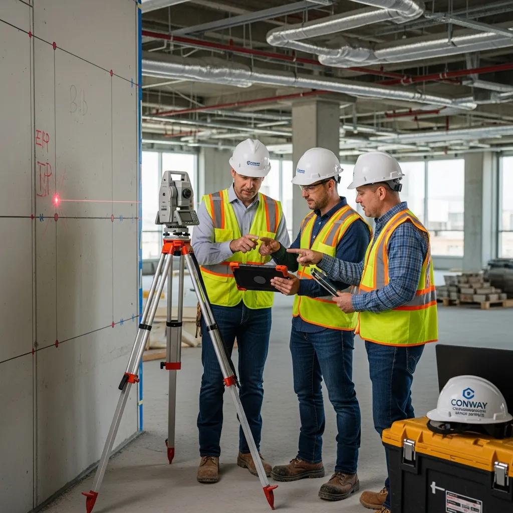
Conway Coordination and Layout Services (CCLS) provides focused RTS layout and BIM/VDC integration services that deliver precise MEP stakeout, verification, and documentation for complex projects. CCLS combines Trimble RTS deployment with VDC workflows to perform control establishment, coordinate import, stakeout, and final verification reporting. Our approach emphasizes close coordination with design teams and prefabrication partners, turning validated models into field‑verified reality while maintaining traceable QA records. Below is a concise process overview and a compact case table summarizing representative project outcomes from the CCLS portfolio.
The CCLS process for RTS layout can be summarized in discrete steps and deliverables.
| Project | Challenge | RTS/BIM Action Taken | Outcome (time/cost saved) |
|---|---|---|---|
| Roper Project (Charleston, SC) | Complex healthcare MEP routing | Control setup, model coordinate stakeout, verification logs | Reduced on‑site rework and improved installation sequencing |
| Confidential Pharmaceutical Facility (Western NC) | Tight tolerance mechanical penetrations | Clash resolution, precise anchor bolt verification | Improved prefabrication fit; schedule adherence |
| Confidential Project (Siler City, NC) | Dense overhead hanger layout | Hanger pattern stakeout and verification | Minimized field adjustments; saved nearly $30,000 in rework avoidance |
This project table demonstrates how CCLS pairs RTS and BIM to improve constructability on healthcare, pharmaceutical, and commercial jobs.
What Is the CCLS Process for Robotic Total Station Layout and Verification?
CCLS follows a structured process that begins with pre‑site planning and BIM coordination, proceeds to control establishment and precise stakeout, and concludes with verification reporting and as‑built delivery. The phased approach includes model review and clash resolution in the VDC environment, defining project datum and control points, loading validated coordinates into the RTS controller, executing stakeout with documented deviations, and producing verification deliverables for BIM integration. Each phase yields tangible deliverables—coordinate lists, verification logs, and reconciliation reports—that support traceability and reduce ambiguity between trades.
Which Case Studies Demonstrate CCLS’s Success in MEP Precision and Cost Savings?
CCLS’s portfolio includes projects where RTS‑driven workflows reduced rework and improved prefabrication alignment across healthcare and pharmaceutical facilities. For example, one confidential project used precise anchor bolt verification to avoid costly corrections during equipment setdown; another healthcare project improved hanger sequencing and reduced installation hours through coordinated RTS stakeout. Reported outcomes show schedule and cost improvements, with one instance saving nearly $30,000 in avoided rework after model‑driven layout and verification were performed before fabrication.
These case outcomes illustrate the ROI of integrating RTS with VDC workflows and explain why clients select CCLS for similar engagements.
Why Choose Conway Coordination and Layout Services for Your Next MEP Layout Project?
Conway Coordination and Layout Services offers clear advantages for teams seeking reliable RTS‑based MEP layout: specialized Trimble RTS expertise, integrated VDC/BIM processes, single‑operator layout efficiency, and project‑proven outcomes across healthcare, pharmaceutical, and commercial sectors. The combination of precise stakeout, verification documentation, and coordination with prefabrication partners reduces GC risk and supports tighter schedules. Below are the specific value propositions that distinguish CCLS and a short action list for initiating a consultation.
Key CCLS value propositions:
- Precision‑focused RTS workflows with emphasis on QA and documentation.
- VDC/BIM integration to eliminate clashes before field layout.
- Operational efficiency through single‑person RTS deployment.
- Demonstrated project outcomes, including quantified rework avoidance.
If you are evaluating RTS‑enabled layout services, include the following in your initial inquiry:
- Project type and primary MEP scope.
- Expected schedule milestones and critical‑path activities.
- Available BIM models and preferred coordinate system.
- Tolerance requirements for anchors, hangers, or penetrations.
This guidance helps teams prepare before engaging a layout specialist. The next section explains CCLS’s differentiators and how to request a consultation.
What Unique Value Propositions Does CCLS Offer in Robotic Total Station Layout?
CCLS highlights several strengths in RTS layout: a single‑person RTS operational model that reduces site labor, close VDC/BIM collaboration that prevents downstream clashes, and sector experience that aligns layout tolerances with industry requirements such as healthcare and pharmaceutical installations. These capabilities enable reliable stakeout, thorough verification reporting, and coordinated prefabrication support that reduce schedule risk. The combined effect is fewer field errors and faster installation velocity for MEP trades.
These differentiators set up a clear next step for teams ready to align scope and schedule, described below.
How Can You Request a Consultation for Precise MEP Layout Services?
To request a consultation, clarify the project’s scope, BIM readiness level, and critical tolerances, and reference Conway Coordination and Layout Services—ask for Nathan Conway as the primary contact. Provide model files, a brief schedule overview, and a list of critical deliverables or tolerances to enable an effective initial evaluation. After your inquiry, expect an alignment call to confirm control requirements, coordinate systems, and verification deliverables before a site visit or proposal is scheduled.
Practical next steps summary:
- Compile model files and specify the coordinate datum.
- List critical MEP tolerances and prefabrication needs.
- Request a consult with Conway Coordination and Layout Services and ask for Nathan Conway.
These steps set expectations for an efficient consult and align project teams for precise, model‑driven MEP layout execution.
Frequently Asked Questions
What types of projects benefit most from Robotic Total Station technology?
RTS is especially valuable on complex projects that demand high precision—healthcare facilities, pharmaceutical plants, and commercial buildings. These jobs often include intricate MEP systems where accurate layout prevents costly rework and meets strict tolerances. Projects using prefabrication benefit significantly because RTS helps ensure components fit together on site, reducing installation time and improving overall efficiency.
How does Robotic Total Station technology integrate with existing construction workflows?
RTS integrates with existing workflows by adding digital precision to traditional methods. BIM coordinates can be imported directly into the RTS controller, smoothing the transition from design to field execution. This integration supports real‑time verification and documentation so stakeholders have accurate data throughout the project lifecycle. Aligning digital models with physical layouts reduces errors and improves collaboration across teams.
What training is required for operators of Robotic Total Station systems?
Operators need training in equipment setup, calibration, and the software used for BIM integration. Typical training covers RTS setup, data collection methods, and how to read verification logs. Familiarity with BIM tools and construction fundamentals is also helpful. Many providers offer targeted training to ensure operators can use RTS effectively on site.
Can Robotic Total Station technology be used for retrofitting existing buildings?
Yes. RTS is effective for retrofits because its precision enables accurate measurements and layout adjustments when integrating new systems into older structures. RTS helps document existing conditions and aligns new installations with existing infrastructure, reducing conflicts and rework. This capability is particularly useful in renovation projects with tight spaces and legacy layouts.
What are the cost implications of implementing Robotic Total Station technology?
While initial RTS investment may be higher than traditional methods, the long‑term cost picture often improves. RTS reduces rework, shortens schedules, and streamlines coordination—factors that cut labor and contingency costs. For many projects, the return on investment appears in reduced corrective work and improved productivity.
How does Robotic Total Station technology enhance safety on construction sites?
RTS improves site safety by reducing the number of personnel needed for layout tasks, which limits congestion and potential hazards. A single operator can manage stakeout operations instead of multiple people working closely together. RTS accuracy also reduces on‑site adjustments that can create unsafe conditions. Getting installations right the first time contributes to a safer jobsite overall.
Conclusion
Robotic Total Station technology significantly improves MEP layout accuracy, productivity, and cost efficiency, reducing rework and tightening project timelines. Integrated with BIM workflows, RTS helps construction teams execute precise layouts with confidence. Working with a specialist like Conway Coordination and Layout Services lets you capture these benefits on your next project. Contact us to learn how RTS can streamline your layout, verification, and prefabrication processes.