Streamlining Renovation Projects with 3D Scanning for Accurate As‑Built Documentation and Faster Construction
Successful renovations start with a reliable picture of the existing conditions. 3D scanning delivers high‑fidelity as‑built documentation that reduces uncertainty and speeds decisions. This guide walks through reality capture—3D laser scanning and LiDAR—explaining how point cloud data powers scan‑to‑BIM, clash detection, and Virtual Design & Construction (VDC) coordination to simplify renovation workflows. You’ll get practical steps for turning scans into usable BIM models, examples for retrofits and historic preservation where non‑invasive surveys matter, and clear metrics for cost and schedule advantages. We also note where to involve specialized providers for targeted Scan to BIM and model coordination. Keywords such as renovation scanning, scan to BIM, point cloud data, and clash detection in renovations are used to keep this resource discoverable and immediately usable.
How 3D Scanning Improves Efficiency and Accuracy on Renovation Projects
3D scanning captures dense, georeferenced point clouds that reflect existing conditions at near‑millimeter fidelity. That verified baseline lets teams check assumptions before demolition or retrofit begins, cutting measurement errors and enabling remote dimension verification. Designers, contractors, and owners use the same digital reference to shorten RFIs and speed procurement. When point clouds feed coordination workflows, MEP, structural, and architectural teams find clashes earlier and plan work with fewer surprises. The list below summarizes the primary efficiency gains and shows how Scan to BIM and VDC build on captured data.
Direct benefits of 3D scanning for renovation projects include:
- Reduced measurement errors: Point clouds replace tapes and hand sketches for critical dimensions and clearances.
- Faster verification: Remote review of scanned areas reduces site visits and accelerates approvals.
- Improved coordination: Accurate geometry enables earlier clash detection and less on‑site rework.
- Smarter procurement: Verified measurements improve material takeoffs and cut overordering.
These improvements translate to fewer change orders and cleaner handoffs to construction teams — which naturally leads into how the scanning technology works on renovation projects.
What Is 3D Laser Scanning and How Does It Help Renovations?
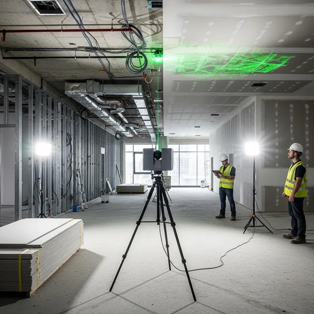
3D laser scanning—a type of terrestrial LiDAR or reality capture—uses rotating lasers and high‑resolution sensors to sample surfaces and create dense point clouds that represent building geometry. Scanners collect millions of points with color and intensity values, capturing walls, MEP runs, structure, and architectural detail. Field gear typically includes terrestrial laser scanners and positioning tools such as robotic total stations; those systems establish control networks and ensure accurate scan registration across complex sites. Standard deliverables include registered point clouds, section shots, and measured outputs that feed directly into modeling and BIM workflows for retrofit design, permitting, and construction layout. Knowing scanner capabilities and expected deliverables helps balance schedule, cost, and required fidelity when planning a survey.
How 3D Scanning Cuts Errors and Rework on Renovations
Accurate as‑built capture eliminates many common error sources—outdated drawings, concealed conditions, and manual measurement mistakes—that cause rework and schedule slips. With a verified baseline, teams run clash detection and solve conflicts in the design phase rather than in the field, avoiding costly interruptions during fit‑out and MEP installation. A common win is identifying obstructing structural elements before MEP prefabrication, preventing remanufacture and site delays. Use the short checklist below to focus on high‑impact risk reductions during scanning.
Practical checklist to reduce on‑site risk:
- Establish control and reference points: Set stable benchmarks for scan registration and future verification.
- Capture concealed areas early: Scan mechanical rooms and chases prior to demolition to reveal conflicts.
- Validate critical dimensions: Confirm doorways, shafts, and corridor clearances against design needs.
- Integrate scans into procurement: Use verified geometry for prefabrication and accurate material ordering.
Applying these steps reduces RFIs and change orders and increases confidence in downstream design decisions.
When teams prefer an external partner, Conway Coordination and Layout Services (CCLS) brings focused reality‑capture and layout expertise to renovation work. CCLS uses Trimble Robotic Total Station technology and proven scan workflows to deliver registered point clouds and model‑ready data that integrate into coordination and construction layout processes. Engaging a provider early helps lock survey scope and maximize the value of captured data.
Benefits of Scan to BIM for Modernizing Existing Buildings
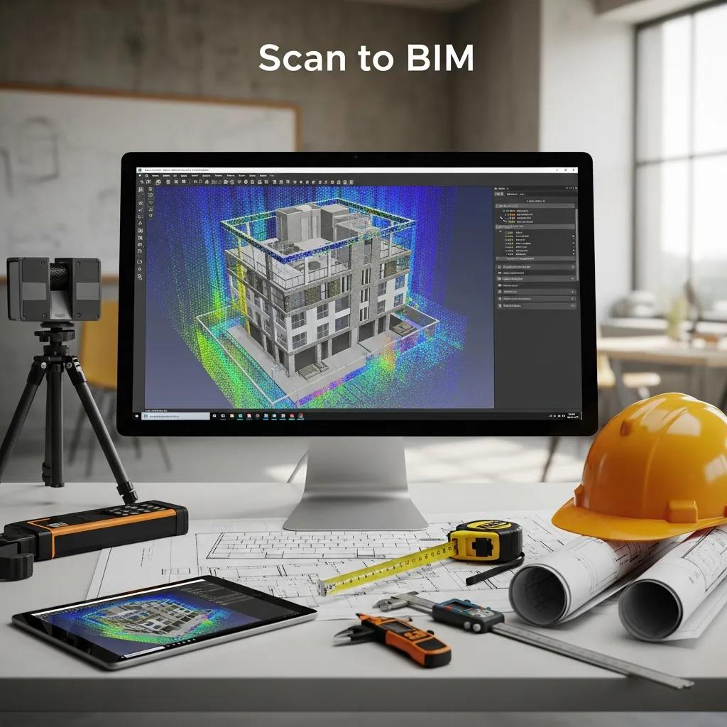
Scan to BIM turns raw point clouds into structured Building Information Models representing walls, slabs, ceilings, and MEP elements at the right Level of Development (LOD). That conversion preserves as‑built conditions, speeds design validation, and creates a reusable model for facilities management after construction. Different project needs require different LODs—models for clash detection use a different fidelity than archival or FM deliverables. Below is a clear overview of how point clouds become BIM and a comparison of typical outputs and toolchains.
Scan to BIM typically follows a repeatable workflow:
- Registration and geo‑referencing: Align scans into a unified coordinate system for integration.
- Cleaning and segmentation: Remove noise and isolate building components for modeling.
- Modeling to LOD: Convert point cloud clusters into parametric BIM elements at the target LOD.
- QA/QC and delivery: Validate dimensions, run clash checks, and export deliverables for design teams and FM.
These steps make reality capture actionable for design, coordination, and digital‑twin use, enabling quicker retrofit decisions and more reliable construction sequencing.
Intro to the table: The table below compares common Scan to BIM outputs, typical turnaround expectations, and the software often used to produce each deliverable.
| Deliverable | Typical Turnaround | Common Software |
|---|---|---|
| LOD 200 architectural shell model | 1–3 weeks per moderate zone | Revit, Autodesk ReCap |
| LOD 300 MEP model for coordination | 2–4 weeks per system zone | Revit, Navisworks |
| As‑built BIM for FM (with metadata) | 3–6 weeks depending on scope | Revit, BIM 360/CMMS export |
This comparison shows how the chosen deliverable drives turnaround and tooling—matching LOD to project phase avoids unnecessary modeling time and cost.
How Scan to BIM Transforms Point Clouds into Usable Models
The conversion starts with registration and control alignment to merge multiple scans into a single, accurately referenced dataset. Technicians then clean the point cloud, remove transient objects, and segment surfaces into walls, slabs, and MEP runs; segmentation guides which elements become parametric objects in the BIM authoring tool. Modeling teams build objects to the agreed LOD and embed attributes like material, finish, and system metadata to support coordination and facilities management. QA/QC includes dimensional checks, clash tests, and client review cycles to confirm fidelity. Clear acceptance criteria for LOD and deliverables at project kickoff streamline reviews and reduce rework during construction.
How BIM Integration Enables Clash Detection and Design Validation
BIM integration allows automated clash detection by overlaying discipline models—architectural, structural, and MEP—against as‑built geometry from scans, surfacing spatial conflicts before crews mobilize. Clash reports rank conflicts by severity and location so project teams can prioritize fixes and resolve issues in coordination sessions, reducing reactive field work. Beyond spatial clashes, teams validate design intent against existing conditions to ensure finishes and penetrations align with structural and service constraints. Regular coordination cycles, supported by shared models and cloud review platforms, make reviews predictable and shorten the time from issue discovery to resolution, which keeps renovation schedules on track.
3D Scanning for Retrofit and Historic Preservation
For retrofit and historic preservation, 3D scanning provides non‑invasive documentation that records fragile materials and complex geometries without contact, enabling conservators and engineers to plan interventions with minimal risk. High‑resolution scans capture ornamental details, mortar joints, and subtle deformations that guide restoration strategies and replace intrusive measuring methods. For heritage projects, metadata and archival standards keep scans useful for future restoration and regulatory review, while photogrammetric overlays deliver color‑accurate references for aesthetic decisions. The examples below highlight scanning use cases for structural assessment, archival records, and conservation planning.
Typical applications in heritage and retrofit work include:
- Archival documentation: Permanent digital records for compliance and future interventions.
- Condition assessment: Quantifying deformations and surface decay for targeted restoration.
- Non‑invasive measurement: Capturing accurate geometry without touching fragile elements.
Advantages of 3D Scanning for Structural Assessment in Retrofits
Point clouds give engineers dimensional data to measure deflections, spot settlement patterns, and compare current geometry to original plans or earlier scans. Quantifiable metrics—plumbness, out‑of‑plane displacement, and span variations—help prioritize repairs and validate retrofit designs against real constraints. Scan‑derived geometry also improves finite element models by providing accurate boundary conditions and member locations, increasing analysis precision versus relying on old drawings. Baseline scans taken before construction enable movement monitoring during retrofit activities, creating an objective record to manage risk and contractual claims. These insights support safer, more cost‑effective retrofit solutions.
How 3D Scanning Enables Non‑Invasive Surveys for Heritage Buildings
Non‑contact scanning preserves heritage fabric by avoiding physical templates, scaffold‑mounted probes, or invasive sampling when documenting delicate elements. Historic scanning protocols emphasize minimal setup impact, controlled access, and detailed metadata capture—scanning date, instrument calibration, and context photos—to support future conservation choices. High‑resolution models let stakeholders review proposed interventions remotely before any physical work begins. Long‑term archiving of point clouds and derived models establishes a defensible record for conservation compliance and future restoration efforts.
Cost Savings and ROI from 3D Scanning in Renovations
3D scanning lowers project risk and recurring costs by reducing rework, shortening design cycles, and improving procurement accuracy—factors that directly affect renovation ROI. Industry benchmarks often show significant drops in field rework and change orders depending on project complexity; those savings come from earlier clash detection, better prefabrication accuracy, and fewer verification site visits. The comparison table below contrasts traditional surveying with 3D scanning across accuracy, time, labor, and impact on rework to help estimate potential savings.
Intro to comparison table: The following table highlights how reality capture stacks up against conventional surveying across core metrics relevant to renovation budgets.
| Approach | Attribute | Typical Value |
|---|---|---|
| Traditional survey | Accuracy | ±25–50 mm typical |
| 3D scanning | Accuracy | ±5–10 mm typical |
| Traditional survey | Time required | Multiple visits, longer field time |
| 3D scanning | Time required | Single comprehensive capture session |
This comparison shows 3D scanning generally improves accuracy and compresses field time, which leads to lower labor costs and fewer surprises during construction.
How Accurate As‑Built Documentation Cuts Material Waste and Delays
Verified geometry from scans improves material takeoffs by replacing assumptions and outdated drawings, reducing over‑ordering and returns on cut materials. Accurate models support off‑site prefabrication of assemblies—duct runs, risers, modular partitions—that install correctly the first time, eliminating costly rework and schedule ripple effects. Less uncertainty also means fewer expedited shipments and less downtime while trades resolve unexpected clashes. These efficiencies lower direct material costs and indirect labor overhead associated with schedule recovery. Integrating as‑built data into procurement and fabrication yields tighter cost control and fewer delay‑related penalties.
Case Examples Showing Financial Benefits of 3D Scanning
Short case snapshots commonly reveal hidden conditions discovered in scans that would otherwise appear during demolition, saving owners contingency spend; for example, finding concealed structural members prior to prefabrication avoids redesign and remanufacture. Another frequent outcome is shorter design cycles—teams converting point clouds to BIM report faster coordination loops, earlier procurement, and reduced mobilization on the critical path. Exact savings depend on project scale, but these scenarios show early reality capture investment often yields net savings through lower rework and faster completion. For a project‑specific ROI, request a tailored assessment based on scan scope and desired deliverables.
When evaluating providers, Conway Coordination and Layout Services (CCLS) focuses on measurable outcomes by combining reality capture with BIM modeling and VDC coordination. CCLS positions precision and coordinated deliverables as the basis for project‑specific ROI calculations and recommends owners request an ROI assessment tied to their scope and schedule.
Intro to EAV table for ROI guidance: The table below outlines how common VDC/BIM components translate into benefits and example impact ranges for renovation coordination.
| Coordination Component | Benefit | Typical Impact |
|---|---|---|
| Clash detection | Reduced on‑site conflicts | 20–40% rework reduction |
| 4D scheduling | Improved sequencing | Shorter critical‑path duration |
| Model coordination | Fewer RFIs | Faster approvals and procurement |
These integration components together reduce waste and accelerate delivery, building the business case for scanning and model coordination on complex renovations.
How VDC and BIM Integration Streamline Renovation Coordination

Virtual Design & Construction (VDC) brings models, schedules, and cost data together to simulate construction sequences and identify access, phasing, and safety constraints before crews arrive. By combining scan‑derived as‑built models with design intent, VDC teams create 4D simulations and sequencing scenarios that reveal clashes in space and time, improving logistics and safety planning. Centralized model repositories and cloud viewers let stakeholders review issues remotely, compress coordination cycles, and speed approvals. The recommended practices below help teams realize VDC benefits on renovation projects.
Recommended VDC and BIM coordination practices:
- Establish model ownership and naming conventions: Keep files consistent and reduce translation errors.
- Schedule regular coordination sprints: Short, focused reviews prevent issue backlog.
- Use 4D simulations for access planning: Visualize sequencing to avoid site bottlenecks.
- Provide handover packages with metadata: Ensure FM can use as‑built BIM for operations.
The Role of VDC in Renovation Workflows
VDC combines multidisciplinary models, schedule data, and cost metrics to evaluate construction sequences virtually, helping teams optimize logistics, access routes, and staging before physical work begins. In renovations—where existing constraints and occupied spaces complicate operations—VDC simulations flag trade conflicts and identify optimal windows for disruptive activities. Typical VDC deliverables include coordinated models, clash logs, 4D animations, and phased site plans that stakeholders use to align expectations and plan procurement. When VDC is paired with Scan to BIM, teams get a coordinated, validated plan that reduces surprises during execution and supports safer, faster renovations.
How an Integrated Digital Workflow Improves Collaboration
An integrated digital workflow uses shared model repositories, cloud viewers, and standardized data exchanges so owners, designers, contractors, and facilities managers work from one authoritative dataset, reducing miscommunication. Shared platforms support markups, issue tracking, and version control, speeding approvals and keeping changes auditable. Deliverables aimed at facilities management—like as‑built BIM with searchable metadata and asset tagging—ensure handoffs remain useful long after construction. Clear documentation standards and agreed handover packages smooth the transition from construction to operations, maximizing long‑term value from the initial scanning investment.
Conway Coordination and Layout Services (CCLS) offers integrated VDC and BIM modeling services tailored to renovation projects, combining reality capture, model coordination, and construction layout with a precision‑first approach. As a family‑operated firm using industry‑standard layout technology and coordinated model workflows, CCLS helps renovation teams turn scan data into clash‑free execution and reliable handover documentation. Interested project teams can request a consultation with Nathan Conway to discuss scope and deliverables.
- Benefit summary: VDC reduces coordination friction and prevents on‑site surprises through synchronized models and schedules.
- Operational tip: Align model LOD expectations early to avoid wasted modeling effort.
- Handover focus: Deliver as‑built BIM with searchable metadata for FM use.
These recommendations reinforce the article’s core point: accurate capture, disciplined modeling, and integrated coordination deliver measurable improvements in renovation efficiency and risk mitigation.
Frequently Asked Questions
What types of projects benefit most from 3D scanning technology?
3D scanning is especially valuable for renovation projects, historic preservation, and retrofits—any scope where precise documentation of existing conditions matters. It’s a big advantage in complex structures, sites with intricate geometry, or work involving fragile materials. Projects that need frequent coordination between MEP, structural, and architectural teams also see major benefits from scan‑based workflows.
How does 3D scanning affect the overall timeline for renovation projects?
When used early, 3D scanning typically shortens overall schedules by speeding documentation and design phases. Accurate as‑built data reduces rework and miscommunication, enables faster verification of conditions, and accelerates procurement. Integrated with BIM workflows, scans enable earlier clash detection and resolution, which helps keep construction on schedule.
What are the limitations of using 3D scanning in renovations?
3D scanning has important advantages, but there are limits: equipment and software costs can be high for smaller firms, and there’s a learning curve for capture and point‑cloud processing. Some materials—highly reflective or transparent surfaces—require special techniques, and poor planning or execution can yield inaccurate data. Proper project scoping and experienced operators are key to avoiding those pitfalls.
How can teams ensure the quality of data captured through 3D scanning?
Follow best practices: establish stable control points for accurate registration, do thorough pre‑scan planning, and choose scanning settings that suit the environment. Keep equipment calibrated and post‑process point clouds to clean and segment data. A QA/QC process with dimensional checks and client review cycles further ensures reliable deliverables.
What role does training play in successful 3D scanning implementation?
Training is essential. Skilled operators capture better data, and trained modelers convert point clouds into useful BIM assets more efficiently. Ongoing training keeps teams current with new hardware and software capabilities, which helps them apply evolving techniques and improve project outcomes.
Can 3D scanning be used for facilities management after renovation projects?
Yes. As‑built BIM models derived from scans make practical digital twins for facilities management. FM teams can use them to locate assets, plan maintenance, and manage space. Embedded metadata supports scheduling, compliance, and lifecycle decisions—so scan‑to‑BIM deliverables provide long‑term value beyond construction.
Conclusion
3D scanning brings clarity and precision to renovation work, reducing errors and streamlining coordination from design through handover. Accurate as‑built documentation helps teams make informed decisions, avoid costly rework, and finish projects faster. If you’d like to explore how our services can simplify your next renovation, contact Conway Coordination and Layout Services to discuss scope, deliverables, and a project‑specific plan.