Precision 3D Laser Scanning for Renovation Projects in Jacksonville, FL: Enhancing Accuracy and Efficiency
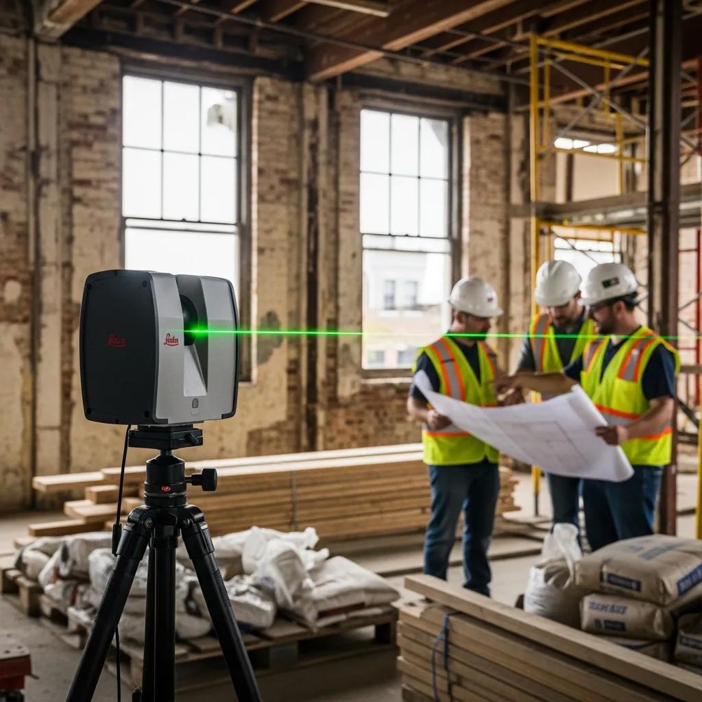
3D laser scanning captures highly detailed spatial data to document existing building conditions and directly solves the core renovation problem: inaccurate as‑built information that causes delays and costly rework. By producing millimeter‑level point clouds and scan‑derived deliverables, reality capture gives designers and contractors the verified measurements they need to make faster, evidence‑based decisions that reduce uncertainty and keep schedules on track. This piece explains why 3D laser scanning matters for Jacksonville renovations, how reality capture improves outcomes, which specialized applications deliver the most value locally, and a practical, step‑by‑step workflow from site assessment through BIM deliverables. You’ll see how LiDAR scanning, Trimble Robotic Total Station checks, and scan‑to‑BIM modeling support MEP coordination, historic preservation, prefabrication, and digital‑twin creation — all framed around actionable choices and predictable results when you work with a regional provider that links scanning to BIM and VDC processes.
Why Is 3D Laser Scanning Essential for Renovation Projects in Jacksonville?
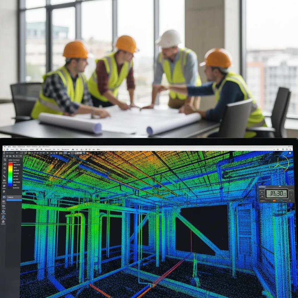
3D laser scanning is essential because it creates a verifiable, high‑resolution record of existing conditions that replaces unreliable or outdated drawings — a single source of truth teams can trust. The method is simple and proven: terrestrial LiDAR and targeted photogrammetry capture millions of measurement points to form a point cloud designers and trades use for planning and verification. That verified dataset reduces change orders, improves prefabrication accuracy, and shortens approval cycles for permitting and contractor buy‑in. In Jacksonville — where older buildings, coastal exposures, and complex MEP systems are common — accurate as‑built documentation prevents surprises during demolition and retrofit work, lowering both schedule and cost risk for local projects.
Here are three primary advantages that make scanning indispensable for renovation work in the region:
- Accuracy: Millimeter‑accurate point clouds remove dimensional uncertainty for design and fabrication, so teams build to the right dimensions the first time.
- Reduced Rework: Reliable data cuts RFI volume and costly field corrections, saving time and budget on active job sites.
- Faster Timelines: Rapid capture and streamlined scan‑to‑BIM workflows accelerate design and prefabrication, helping projects meet tighter schedules.
Those benefits translate into measurable improvements on real projects, and they set the stage for how scanning prevents errors and speeds delivery in practice.
How Does 3D Scanning Eliminate Costly Errors and Rework?
Accurate 3D scans eliminate errors by creating an objective measurement baseline that designers and contractors reference throughout a renovation, cutting ambiguity and misinterpretation. Point cloud data enables clash detection and precise prefabrication dimensions, which minimizes in‑field adjustments and change orders during installation. For example, using scan‑derived models to pre‑validate MEP routing or structural penetrations reduces guesswork and prevents expensive on‑site modifications. The point cloud also serves as an auditable record teams can use to resolve disputes or verify scope during progress reviews. This single‑source approach closes gaps between survey, design, and construction teams, improving coordination and reducing rework‑related delays on the job.
Lasting reductions in errors and claims require integrating scan data into BIM and coordination platforms — a topic we cover next as it relates directly to schedule acceleration.
In What Ways Does 3D Scanning Accelerate Renovation Timelines?
3D scanning shortens timelines by compressing site measurement into hours rather than days and enabling parallel workflows where design and procurement proceed while site work continues. Fast capture reduces repeat site visits and speeds decisions because stakeholders review the same verified point cloud remotely. Prefabrication benefits immediately: shop drawings and modular components can be manufactured to exact scan‑derived dimensions, cutting installation time and limiting plant or facility downtime. Early clash detection in Revit or Navisworks prevents late‑stage design stalls and supports more reliable scheduling. Together, these time savings shorten procurement cycles and let contractors sequence work with greater confidence.
Those faster timelines depend on consistent QA of scan data and smooth handoffs into modeling tools, which brings us to the broader set of benefits reality capture services provide.
What Are the Key Benefits of Reality Capture Services for Jacksonville Renovations?
Reality capture services deliver practical benefits that improve cost certainty, safety, coordination, and regulatory compliance for renovation projects in Jacksonville. Core deliverables — raw point clouds, 2D CAD extractions, modeled BIM files, and digital‑twin packages — serve different stakeholders (surveyors, designers, fabricators, facility managers), so choosing the right output is critical to success. These services also reduce time spent in hazardous areas and give accurate spatial references for temporary works and demolition, improving site safety. In procurement and bidding, reliable quantities and dimensions from scans produce more accurate estimates and fewer surprises during execution — a distinct advantage for local owners and contractors.
The table below compares common deliverables to help teams select the right product for their objectives:
| Purpose | Characteristic | Typical Delivery Time |
|---|---|---|
| Point Cloud (raw) | High‑resolution measurement points in E57/PTS format for survey verification and downstream modeling | 1–5 days after capture |
| 2D CAD Drawings | Extracted plan, elevation, and section lines for permitting and retrofit documentation | 3–7 days after processing |
| 3D BIM Model | LOD‑based Revit model from point cloud for coordination and fabrication workflows | 1–4 weeks depending on LOD |
| Digital Twin Package | Integrated BIM + metadata + 360 imagery for operations and asset management | 2–4 weeks with asset tagging |
This comparison clarifies trade‑offs between turnaround, fidelity, and intended use. Choose the deliverable that matches whether your priority is quick verification, coordination‑ready models for clash detection, or long‑term facility data for operations.
How Does Accurate As-Built Documentation Improve Project Outcomes?
Accurate as‑built documentation improves project outcomes by enabling precise quantity takeoffs, reliable budgets, and fewer scope changes during construction. When contractors and estimators use scan‑derived drawings, bids reflect actual conditions instead of assumptions, which reduces contingency buffers and surprises. During construction, verified dimensions lower RFIs and change orders because designers and field teams work from the same dimensional dataset. For owners, comprehensive documentation supports lifecycle planning and simplifies future renovations or maintenance. These benefits compound into lower total project cost and better schedule adherence across renovation phases.
Accurate deliverables also promote collaborative coordination processes — where scan‑to‑BIM and clash detection become practical, day‑to‑day tools for alignment.
How Does 3D Scanning Enhance Collaboration and Clash Detection?
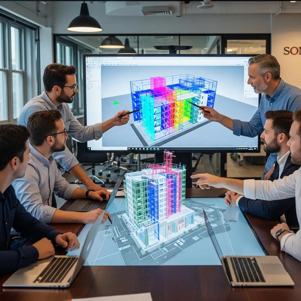
3D scanning improves collaboration by converting point clouds into BIM models used in coordination platforms for multi‑trade clash detection and resolution before fieldwork begins. Point cloud‑to‑Revit conversion and Navisworks aggregation let MEP, structural, and architectural teams visualize interferences and resolve spatial conflicts virtually. Regular coordination cycles using the same scan‑derived model reduce miscommunication and enable trades to prefabricate components with confidence. Overlaying TruViews or 360 imagery adds visual context to modeled geometry, shortening the design‑validation loop and minimizing on‑site problem solving.
Effective coordination depends on consistent data formats and version control so everyone works from the latest model — which leads to industry‑specific applications where these techniques deliver the most value.
Which Specialized Applications Use 3D Scanning in Jacksonville Renovation Projects?
Several specialized applications rely on 3D scanning to manage complexity and protect critical assets during Jacksonville renovations. Historic preservation, commercial and industrial retrofits, healthcare facility upgrades, and MEP‑heavy renovations commonly call for reality capture to balance precision with non‑intrusive documentation. Each application has unique challenges — fragile materials at historic sites, dense plant piping in industrial retrofits, and tight tolerances in healthcare — and 3D scanning provides tailored deliverables to mitigate those risks. The best method (terrestrial laser scanning, mobile mapping, or photogrammetry) depends on scale, required resolution, and site access constraints.
The table below compares three common applications so teams can match scanning approaches to project needs:
| Application | Key Challenge | Typical Deliverable |
|---|---|---|
| Historic Preservation | Non‑invasive documentation of fragile fabric and ornate façades | High‑res meshes, orthophotos, archival point cloud |
| Commercial/Industrial Retrofit | Complex MEP and structural overlays in active facilities | Scan‑to‑BIM Revit model with clash analysis |
| Healthcare/Pharma Upgrades | Tight tolerances and regulatory compliance during retrofits | LOD 300–400 BIM, as‑built verification reports |
Picking the right application approach ensures scanning outputs support restoration, retrofit, or compliance goals and reduces downstream coordination friction.
How Is 3D Scanning Applied in Historic Building Preservation?
For historic preservation, 3D scanning provides non‑contact documentation of façades, ornamental features, and interior geometries that are too delicate for conventional measurement. High‑resolution scans produce detailed meshes and orthophotos used to create restoration drawings, fabricate replacement elements, and archive conditions for future study. Combining photogrammetry with terrestrial LiDAR captures both fine surface detail and volumetric context in one survey package. These archival datasets support grant applications, conservation planning, and informed restoration sequencing while preserving original fabric for posterity.
Preservation teams then use scan‑derived models to guide material choices and to plan minimally invasive interventions that respect historic integrity.
What Role Does 3D Scanning Play in Commercial and Industrial Retrofits?
In commercial and industrial retrofits, 3D scanning supports detailed MEP coordination, off‑site prefabrication of modules, and accurate structural overlays that cut plant shutdown time. Point clouds let engineers route new systems around existing infrastructure with predictable clearances, enabling off‑site fabrication of assemblies that fit on first install — a major advantage where downtime is costly. Scans also enable phased retrofit planning by providing verified geometry to simulate sequencing and detect clashes early. The result: lower execution risk and faster return to operations after retrofit work.
These application scenarios illustrate practical workflows; next we break down those workflows into a clear, step‑by‑step process for renovation projects.
What Is the Step-by-Step 3D Scanning and BIM Process for Renovations in Jacksonville?
A standardized step‑by‑step process produces consistent outcomes from scan capture through BIM integration, shortening delivery times and improving coordination. Core steps include project consultation and scoping, on‑site data capture with LiDAR and targeted imagery, point cloud processing and QA, and final deliverables such as 2D CAD, Revit models, or digital twins integrated into client systems. Each step assigns responsibilities and typical durations so teams can plan around capture windows and deliverable turnarounds. The numbered workflow below is concise and practical for project managers planning engagement.
- Step 1 — Initial consultation and scope definition with deliverable selection and access planning to align expectations early.
- Step 2 — On‑site data capture using terrestrial LiDAR, photogrammetry, and survey control checks for reliable inputs.
- Step 3 — Point cloud registration, cleaning, and QA, with E57/RCP outputs prepared for modelers and surveyors.
- Step 4 — Scan‑to‑BIM modeling, clash detection, and delivery of Revit/CAD files plus visualizations ready for coordination and fabrication.
Following these steps creates consistent handoffs between field crews, modelers, and coordination teams and supports faster procurement and fabrication cycles on Jacksonville projects.
Below is a process table that clarifies responsibilities and outcomes for realistic project planning:
| Phase | Responsible Party | Typical Duration | Outcome / Benefit |
|---|---|---|---|
| Consultation | Client + Provider | 1–5 days | Defined scope, deliverable plan, access schedule — early alignment avoids surprises. |
| Data Capture | Field Survey Team | 1–3 days | Raw point cloud and imagery for site verification and modeling inputs. |
| Processing & QA | Processing Engineer | 2–7 days | Registered point cloud, error checks, control validation — data you can trust. |
| Modeling & Delivery | BIM Modeler | 1–4 weeks | Revit model, clash reports, fabrication‑ready drawings that speed installation. |
This table helps project leaders allocate time and resources realistically and shows how each phase produces a tangible artifact that reduces downstream risk.
Local providers that combine scanning with BIM/VDC processes can shorten integration time. Conway Coordination and Layout Services, for example, positions scanning inside a scan‑to‑BIM and VDC pipeline that emphasizes Trimble Robotic Total Station checks and model integration to client workflows. Project teams should request a scoped assessment to align deliverables with schedule and tolerance requirements.
What Happens During Initial Consultation and Project Assessment?
Initial consultation establishes project objectives, required deliverable fidelity (point cloud, CAD, BIM), access constraints, and any safety or operational limitations that affect capture planning. The consultant collects existing drawings, facility schedules, and points of contact, then recommends capture methods — terrestrial LiDAR for interior geometry or photogrammetry for façades — based on the needed resolution. Timelines and tolerance thresholds are agreed up front so modelers know the required LOD for Revit deliverables and coordination. Early alignment reduces surprises and ensures the point cloud supports intended design and fabrication use cases.
The assessment also identifies opportunities for layout verification using control surveys like Trimble Robotic Total Station to tie scan data to construction coordinates.
How Is High-Precision Data Captured Using LiDAR and Trimble Technology?
High‑precision capture combines LiDAR scanning, targeted imagery, and survey control to produce datasets fit for BIM modeling and layout verification. LiDAR delivers dense point clouds with millimeter‑level detail for structural and MEP geometry, while photogrammetry adds high‑resolution texture for façades and finishes. Trimble Robotic Total Station technology supplies control and layout verification, enabling field staking and as‑built checks that link models to site coordinates for construction staking. Standard delivery formats include E57 and RCP for point clouds and Revit for modeled outputs, and QA practices include control checks, registration residual analysis, and spot validations against independent survey points.
These capture practices ensure models built from scan data are reliable for fabrication and field layout tasks.
How Does Conway Coordination and Layout Services Deliver Superior 3D Scanning Solutions in Jacksonville?
Conway Coordination and Layout Services (CCLS) provides integrated reality capture and BIM/VDC consulting tailored to renovation projects, focusing on precision and smooth workflow integration across scan‑to‑model deliverables. The company pairs Trimble Robotic Total Station control with 3D scanning to ensure accurate control and layout verification and positions scan data for direct use in coordination and prefabrication workflows. CCLS emphasizes adaptability and reliability, offering end‑to‑end services from point cloud capture to BIM modeling and VDC consulting that help teams move from survey to installation with minimal rework. For project teams that want a single local partner bridging field verification and BIM integration, CCLS is a practical choice that mixes regional knowledge with specialist technology.
What Local Expertise and Technology Does CCLS Bring to Renovation Projects?
CCLS pairs regional renovation experience with technology like Trimble Robotic Total Station and modern 3D scanning equipment to deliver precise survey control and scan‑to‑BIM services. The firm’s offerings include point cloud capture, point cloud‑to‑Revit conversions, and VDC consulting to align models with contractor workflows. By combining survey‑grade control with BIM integration, CCLS helps clients cut field verification time and enables accurate prefabrication and installation. Project teams benefit from this coordination with fewer iterations and higher‑fidelity as‑built models for clash detection and fabrication.
These capabilities make CCLS a hands‑on collaborator for Jacksonville projects that demand coordinated, technology‑driven renovation workflows.
How Do Client Testimonials Reflect CCLS’s Commitment to Precision and Efficiency?
Client testimonials and case examples provide social proof of CCLS’s focus on precision and efficient integration of scan data into construction workflows; specific quotes should be drawn from verified project materials. Testimonials commonly point to measurable outcomes such as fewer field changes, accurate fabrication fit, and smoother coordination meetings when scan‑based models are used. Citing named projects and outcomes — when permitted — connects the provider’s differentiators to real improvements in schedule and cost control. Project managers should request case studies or references to confirm that the provider’s process meets their tolerance and schedule needs.
Using client examples to set expectations closes the loop between promised capabilities and day‑to‑day results for renovation teams.
What Are Common Questions About 3D Scanning for Renovation Projects in Jacksonville?
Clients often ask about pricing drivers, turnaround times, applicability to MEP coordination, and deliverable formats; clear answers set realistic expectations for procurement and scheduling. Pricing depends on project size, site access, required deliverable fidelity (raw point cloud versus LOD 300–400 BIM), and any safety or downtime constraints that require phased capture. Turnaround times vary by deliverable and LOD but are predictable when the project follows a standard workflow of consultation, capture, processing, and modeling. Below are the most common cost and planning factors to discuss during scoping.
- Project Size: Square footage and areas to be scanned drive field time and line‑of‑sight setups.
- Complexity: Dense MEP, intricate structural geometry, or ornate historic fabric increases processing and modeling effort.
- Deliverables: Raw point clouds are faster; LOD 300–400 BIM models require more modeling time and QA.
- Access & Downtime: Restricted or live environments may need phased capture windows and coordination with operations.
These factors determine the final quote — request a scoped proposal after assessment to get an accurate price and schedule estimate tailored to your project.
What Is the Typical Cost of 3D Laser Scanning Services in Jacksonville?
Costs aren’t one‑size‑fits‑all. 3D laser scanning pricing is driven by site area, complexity, chosen deliverables, and project constraints that affect field crew time and modeling effort. Key pricing drivers include the number of scan setups, the required LOD for BIM deliverables, and any specialized surveys such as control verification with Trimble equipment. Providers typically issue scoped quotes after an initial consultation and site assessment to align deliverables with budget and schedule needs. For accurate budgeting, gather existing drawings, define deliverable expectations, and request a detailed proposal listing scope, assumptions, and turnaround times.
This approach makes cost estimates reflect real project variables rather than generic price points.
Can 3D Scanning Be Used for MEP Coordination and Facility Upgrades?
Yes. 3D scanning is highly effective for MEP coordination and facility upgrades because scan‑to‑BIM workflows convert measured point clouds into coordination‑ready models used for clash detection and prefabrication. The process supports Revit‑based modeling, Navisworks aggregation for coordination, and generation of fabrication‑level details for off‑site assembly. For facility upgrades, these workflows reduce field‑fit issues and minimize downtime by letting trades prepare assemblies with confidence they will fit as‑built conditions. Integrating scan data with VDC consulting ensures modeled outputs meet the tolerance and documentation requirements needed for high‑precision installations.
Project teams should specify the desired LOD and coordination schedule during scoping to ensure deliverables support MEP prefabrication timelines and installation tolerances.
Frequently Asked Questions
What types of projects benefit most from 3D laser scanning?
3D laser scanning delivers the most value on projects involving historic preservation, commercial and industrial retrofits, and healthcare facility upgrades. These jobs often face complex MEP systems, fragile materials, and strict regulatory requirements. Accurate as‑built documentation from scanning helps mitigate those risks, enabling precise renovations with minimal disruption and better coordination among stakeholders.
How does 3D scanning integrate with Building Information Modeling (BIM)?
3D scanning integrates with BIM by converting point cloud data into detailed 3D models that architects and engineers can use for visualization, clash detection, and design validation before construction. Scan‑derived models plug into common BIM tools, enabling multi‑trade coordination and streamlined workflows that reduce errors and rework during renovation.
What are the limitations of 3D laser scanning technology?
3D laser scanning has limitations. Highly reflective or transparent surfaces can produce noisy data, and initial setup plus point‑cloud processing require specialist skills and time. Costs vary with project complexity and size, which may make scanning less practical for very small projects. Knowing these limits helps teams plan appropriately and choose complementary methods where needed.
How can 3D scanning improve safety on renovation sites?
3D scanning improves safety by reducing the time workers spend in hazardous areas. Detailed point clouds and models let teams plan demolition, temporary works, and sequencing with greater precision, minimizing exposure to unforeseen structural issues. Better planning and visualization lead to safer execution and fewer last‑minute, risky decisions on site.
What is the typical turnaround time for 3D scanning deliverables?
Turnaround depends on complexity and deliverable type. Raw point clouds are often delivered within 1 to 5 days after capture; 2D CAD drawings typically take 3 to 7 days; and 3D BIM models usually require 1 to 4 weeks depending on the LOD specified. Agreeing timelines during the initial consultation sets clear expectations for delivery.
How does 3D scanning support sustainable renovation practices?
3D scanning supports sustainability by enabling precise planning and reducing material waste. Accurate as‑built data helps teams identify opportunities for material reuse and optimized ordering, while prefabrication driven by scan data minimizes on‑site waste and rework. Overall, incorporating reality capture into renovation workflows helps projects use resources more efficiently.
Conclusion
Using 3D laser scanning on Jacksonville renovation projects significantly improves accuracy, reduces costly rework, and accelerates schedules — all of which lead to more predictable, successful outcomes. Reliable as‑built documentation and tight integration with BIM/VDC workflows let teams make informed decisions through every phase of a renovation. If you want to streamline your next project, explore integrated scanning and BIM services with a local partner who understands the regional challenges and delivers measurable results.