3D Laser Scanning in Charlotte, NC — Precise Reality Capture for Construction and Industry
3D laser scanning is a non-contact reality-capture method that produces high-density point clouds with millimeter-level accuracy. In Charlotte, that accuracy helps contractors, MEP trades, and renovation teams verify as-built conditions, coordinate complex systems, and speed prefabrication. This article walks through how scanning captures reliable as-built data, why it often outperforms conventional surveying on complicated sites, and how scan data plugs into BIM and VDC workflows used by today’s contractors and facility managers. You’ll also find the step-by-step workflow from kickoff to delivery, common file types and use cases, industry applications across Charlotte, and how to engage Conway Coordination and Layout Services (CCLS) for local reality-capture work.
What is 3D Laser Scanning and How Does It Benefit Charlotte Construction Projects?
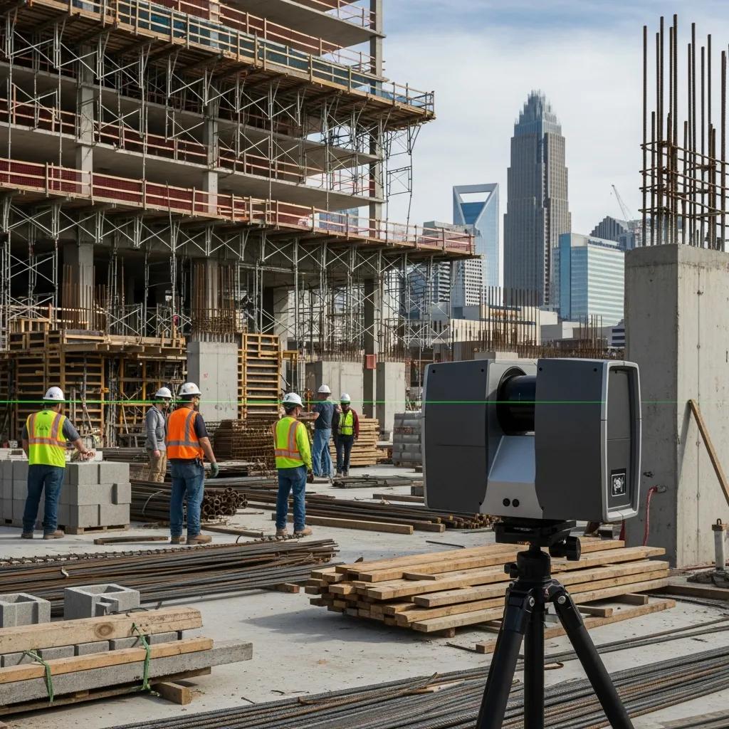
3D laser scanning uses LiDAR to record millions of surface points and produce a dense, three-dimensional record of existing conditions—ideal for accurate as-built documentation and digital twins. Scanners measure distance with time-of-flight or phase-shift returns to generate point clouds with millimeter-grade fidelity. For Charlotte projects, that fidelity lowers rework, speeds coordination between trades, and reduces exposure to risky measurements in active zones. Below we explain how the technology captures dependable as-built data and why teams increasingly choose scanning over traditional surveying on complex jobsites.
Practical benefits construction teams see right away include:
- Millimeter-level accuracy: Dense captures reduce dimensional uncertainty during design and prefabrication.
- Faster site coverage: Complex MEP, structural, and architectural geometry is recorded more efficiently than point-by-point surveys.
- Improved safety and access: Non-contact scanning minimizes the need to enter confined or hazardous areas.
Those gains translate to fewer RFIs, fewer change orders, and stronger schedule confidence for general contractors and specialty trades. The next section details the capture mechanics behind these outcomes.
How Does 3D Laser Scanning Capture Accurate As-Built Data?
Scanners emit laser pulses and measure either the time-of-flight or phase shift of the return to determine precise distances, storing each measurement as a 3D point. A single scan position can return millions of points; multiple positions are registered together using control targets, total station ties, or GNSS where available to create a single, project-aligned coordinate system. QA steps—registration checks, loop-closure verification, and comparisons to survey control—confirm the cloud meets millimeter tolerances. With validated point clouds, BIM modelers and contractors can make design and fabrication decisions based on measured conditions instead of assumptions.
Next, we compare those capabilities with what traditional surveying delivers on real-world sites.
What Are the Key Advantages of 3D Scanning Over Traditional Surveying?
Where conventional surveys provide discrete control points and linear measurements, 3D scanning captures continuous surface geometry and rich context—especially valuable in areas with tight MEP routing, curved architecture, or congested mechanical rooms. A single comprehensive scan can answer many downstream questions and reduce repeat site visits; traditional surveying often requires targeted returns when new questions arise. Scanning complements survey control rather than replaces it, combining accuracy with the contextual detail teams need for clash detection, prefabrication, and visual validation.
Why Choose CCLS for 3D Laser Scanning Services in Charlotte, NC?
CCLS pairs specialized reality-capture expertise with coordination and layout services to deliver a full pathway from field capture to BIM/VDC-ready assets for Charlotte clients.
Family-owned and locally focused, we use proven workflows to produce precise as-built documentation, tailored models, and coordination support that lower downstream risk. CCLS prioritizes millimeter-level accuracy, smooth scan-to-BIM handoffs, and delivery schedules aligned with contractors’ prefabrication and installation needs. Below we summarize the equipment and QA practices that make those results repeatable.
To make value clear, this table maps core features to outcomes you’ll see on projects.
| Service Feature | What It Means | Benefit to Client |
|---|---|---|
| Precision Reality Capture | Millimeter-level point clouds with validated survey control | Less rework and reliable prefabrication |
| Integrated VDC/BIM Workflows | Direct scan-to-BIM conversion and coordination services | Faster clash resolution and coordination cycles |
| Client-Centric Partnership | Collaborative scoping and delivery planning | Deliverables built to meet contractor schedules |
| Comprehensive Layout Services | Field layout and verification tied to scan data | Smoother handoff from model to field execution |
What Technologies and Equipment Does CCLS Use for Precise Scanning?
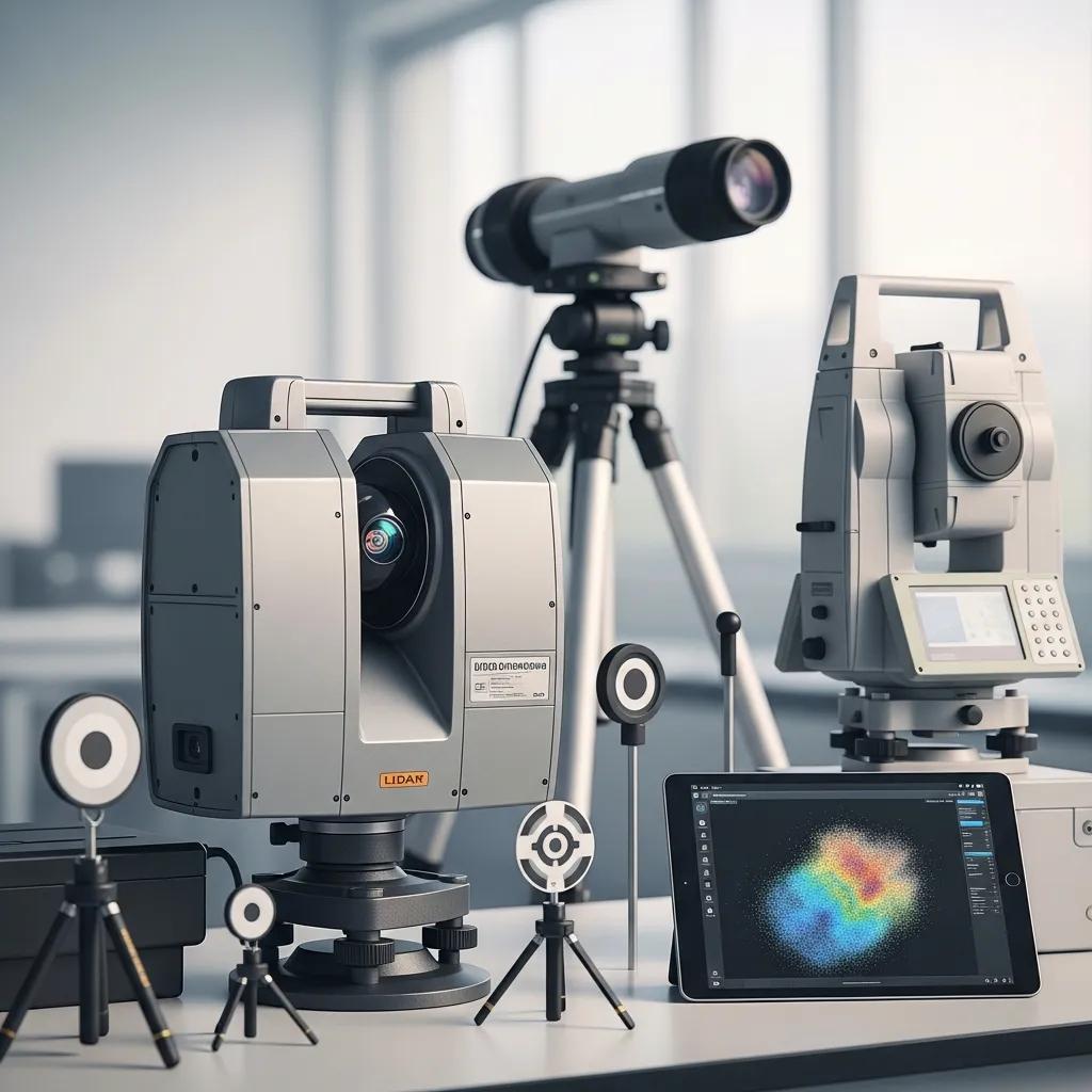
We deploy industry-leading scanners and supporting survey instruments chosen for range, density, and the job at hand: short-range, high-density LiDAR for interiors; long-range scanners for façades and yards; and robotic total stations or GNSS for reliable georeferencing. Data is delivered in standard formats compatible with Revit, Navisworks, and common point-cloud toolchains. Equipment strategy is selected per project—dense interior scans for MEP coordination, long-range captures for exteriors, and hybrid approaches for mixed-use sites—so the capture supports your modeling and installation needs.
Correct hardware choice sets the stage for registration and QA to confirm collected data meets project tolerances and schedule windows.
How Does CCLS Ensure Accuracy and Efficiency in Every Project?
Our QA/QC process is layered: field control setup, redundant scans and overlap, targeted registration checks, and validation against survey control points. In the field we establish control with targets or total station ties and capture overlapping positions to support robust registration. Post-processing combines automated and manual registration, noise filtering, and deviation checks. We manage turnaround by agreeing on deliverable formats up front and using optimized processing pipelines to produce point clouds, CAD extractions, or BIM models on schedule. Typical QA metrics include registration residuals and control-point deviations that verify the point cloud fits project tolerances.
These practices feed a standardized workflow clients can rely on—outlined in the next section.
| Service Feature | Typical Checkpoint | Client-Facing Outcome |
|---|---|---|
| Field Control Establishment | Target setup / total station tie | Georeferenced point cloud |
| Redundant Scans | Overlap and re-scan of complex zones | Stronger registration reliability |
| Post-Processing QA | Residual and deviation reporting | Confidence in delivered assets |
What is the Step-by-Step Process of 3D Laser Scanning at CCLS?
CCLS follows a clear, client-focused workflow from consultation through delivery to reduce uncertainty and align outputs with construction and BIM needs. We begin with a project kickoff to confirm scope, deliverable formats, access windows, and target accuracy. Field capture follows with established safety measures and control setup. Processing, QA, and client review loops refine models or drawings. Final delivery includes packaged assets—point clouds, 2D CAD as-builts, or scan-to-BIM models—plus documentation that supports coordination and installation.
- Consultation: Define scope, access, and deliverables with the client.
- Field Capture: Technicians establish control and collect scans per plan.
- Processing & QA: Registration, cleaning, and verification against control.
- Delivery & Support: Point clouds, CAD/BIM models, and coordination assistance.
This predictable workflow leads into a breakdown of responsibilities, outputs, and typical timeframes.
| Step | Responsible Party | Typical Output/Timeframe |
|---|---|---|
| Project Kickoff & Scope | Client + CCLS | Scope document and schedule (1–3 days) |
| Field Capture | CCLS Field Team | Raw point cloud data (1–5 days on-site depending on size) |
| Processing & QA | CCLS Processing Team | Registered point cloud and QA report (3–10 business days) |
| Deliverable Production | CCLS VDC/BIM Team | CAD/BIM assets and review package (5–15 business days) |
How Is Project Consultation and Scope Defined for Charlotte Clients?
Consultation starts with a quick intake of project goals, existing drawings, photos, access windows, and any known site constraints so deliverables match your coordination and construction needs. We review MEP complexity and site logistics to propose an efficient capture plan and a focused deliverable list. Pricing and timelines are based on area, access, complexity, and the required level of detail for BIM or CAD outputs. Clear scoping up front minimizes surprises and ensures the captured data supports prefabrication, clash detection, and field layout tasks.
That planning informs capture strategy and processing priorities—described next.
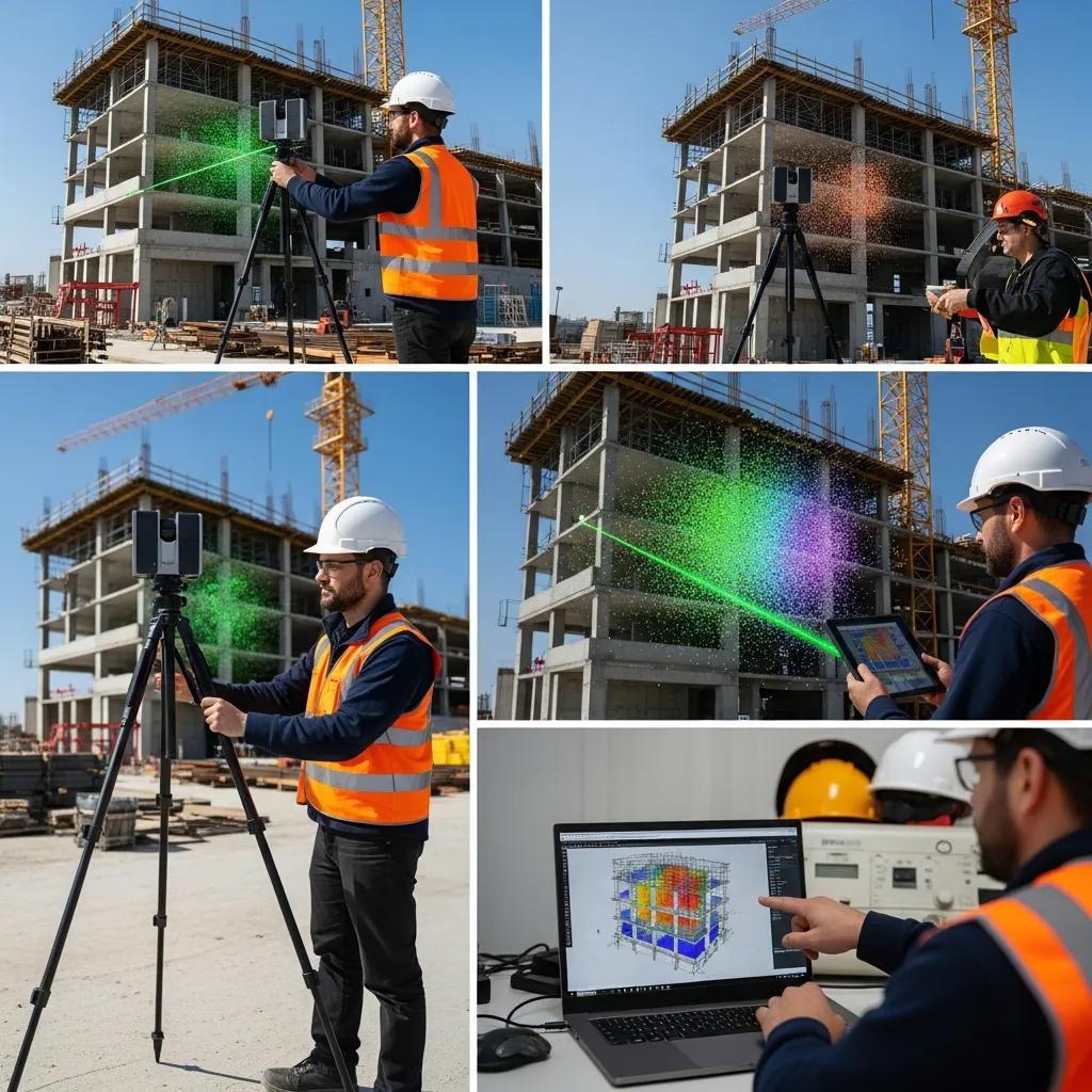
What Happens During On-Site Data Capture and Processing?
On site we establish control, place scan positions for complete coverage, capture high-density scans of critical systems, and collect photos for colorization when needed. Safety protocols and access coordination keep disruption to a minimum, and technicians verify data integrity in the field to avoid gaps. Post-capture processing registers scans, removes noise, and converts the unified cloud into deliverables—cleaned point clouds, slice-based CAD drawings, or modeled BIM elements. Client review loops allow quick clarification or limited rework before final handoff.
Those steps ensure final assets are accurate and immediately usable for downstream construction and coordination workflows.
What Deliverables Can Clients Expect from Charlotte 3D Laser Scanning Services?
Deliverables are scoped to each project but commonly include high-density point clouds in standard formats, dimensioned 2D CAD as-builts, and scan-to-BIM models at agreed Levels of Detail. We select outputs during scoping so they support your objectives—fabrication, clash detection, verification, or archival documentation. Below are the typical deliverables and when to choose each.
- High-density point clouds: Raw spatial data for measurement, modeling, and visualization.
- 2D CAD as-builts: Scaled drawings for permitting, retrofit design, or contractor reference.
- Scan-to-BIM models: Revit models for coordination, clash detection, and prefabrication.
- Registration and control files: Records for georeference and future survey integration.
These assets give teams the digital foundation for precise decisions. The table below summarizes file types, densities, and typical uses.
| Deliverable | Density / Format | Typical Use |
|---|---|---|
| Point Cloud | High-density (.e57, .rcp) | Measurements, clash detection, visualization |
| 2D CAD Drawings | Scaled DWG / PDF | Permitting, retrofit documentation |
| 3D BIM Model | Revit LOD per scope | Coordination, prefabrication, schedule integration |
What Are High-Density Point Clouds and Their Uses?
High-density point clouds are collections of millions of LiDAR returns that map surfaces with fine detail, enabling precise measurement and visualization of complex geometries. Density is commonly expressed in points per square meter or total returns; higher density supports detailed MEP modeling, intricate architectural features, and historical façades. Point clouds power clash detection, dimensional verification, reverse engineering, and scan-to-BIM workflows. Capture strategy and scanner choice directly affect modeling accuracy, so we plan both to meet agreed tolerances.
Knowing point-cloud characteristics helps teams choose the right deliverables for coordination or fabrication—next we cover how those clouds become CAD drawings and BIM models.
How Are 2D CAD Drawings and 3D BIM Models Created from Scan Data?
Scan-to-CAD and scan-to-BIM start by extracting planes, centerlines, and feature geometry from the registered point cloud, then translating those elements into dimensioned CAD drawings or intelligent BIM components. Modeling tools interpret point-cloud slices and fit parametric elements—walls, ducts, conduits—while modelers apply the LOD standards agreed in scope. Verification includes overlay checks between model and cloud, dimensional spot checks, and client review passes to confirm fidelity. Deliverables are exported in client-ready formats and include QA documentation that notes modeling tolerances and assumptions.
This conversion turns captured reality into actionable digital assets for design and construction teams.
How Are 3D Laser Scanning Services Applied Across Charlotte’s Industries?
3D laser scanning supports construction, industrial facilities, healthcare, historic preservation, and commercial projects across Charlotte by providing verified existing-condition data that lowers risk and speeds coordination. In construction, scan data validates installed conditions and aids prefabrication; in industrial settings it maps equipment for upgrades and maintenance; for preservation it creates non-invasive archival records of fragile structures.
Key industry applications and their benefits include:
- Construction verification: Confirm installed conditions and reduce RFIs.
- MEP coordination: Detect clashes and enable off-site prefabrication.
- Industrial upgrades: Map equipment layouts for retrofits and maintenance planning.
- Historic preservation: Produce non-invasive archival records and measured drawings.
How Does 3D Scanning Support Construction Verification and Quality Control?
Scanning supports verification by comparing as-built point clouds to design models to find deviations, quantify tolerances, and generate deviation reports for installers and owners. Typical workflows scan after key milestones, overlay the cloud with the design model, and produce color-coded deviation maps and tabular reports for out-of-tolerance areas. This proactive approach catches issues early, reduces rework, and provides objective evidence for resolving disputes or scope changes—often shortening punch-list cycles and improving handover quality.
What Role Does 3D Scanning Play in Renovation, MEP Coordination, and Historic Preservation?
For renovations, scanning verifies clearances and spatial relationships so designers can plan interventions without invasive demolition. In MEP coordination, scan-derived geometry supports precise clash detection and prefabrication of modular assemblies, speeding installation and reducing field labor. Historic preservation benefits from non-invasive, high-fidelity documentation that records fine surface details and supports conservation planning. Each application uses tailored capture and modeling strategies to respect site constraints—fragile finishes or limited access—while delivering usable digital assets.
These examples show how scanning adapts to different project priorities and prepare teams for the next step: engaging a local provider.
How Can You Get Started with CCLS’s 3D Laser Scanning Services in Charlotte?
Starting with CCLS is straightforward: request a consultation, define scope and deliverables, receive a tailored quote, and schedule capture in agreed access windows. During consultation we ask for site photos, drawings, and access constraints so we can propose an efficient capture plan and realistic timeline. Quotes reflect drivers like square footage, MEP density, required LOD for BIM, and any georeferencing needs. Once engaged, CCLS manages logistics and executes capture and processing on the agreed schedule, with review checkpoints before final delivery.
- Request a consultation: Share project scope, drawings, and access windows.
- Confirm scope & receive a quote: Agree on deliverables, accuracy, and schedule.
- Schedule capture: Coordinate access and perform on-site scanning.
- Review & receive deliverables: Validate outputs and request adjustments if needed.
This simple decision path clarifies what clients should prepare and what to expect next.
What Is the Consultation and Quotation Process for Charlotte Projects?
Consultation focuses on discovery: we review site photos, existing drawings, access windows, and your deliverable needs to prepare a scoped proposal. Pricing drivers include area to be scanned, site complexity (dense MEP or multiple levels), required LOD for BIM models, and any georeferencing or survey-control work. Quotes itemize capture, processing, modeling, and deliverable production so you can see how scope adjustments affect cost and schedule. Post-agreement scope changes are handled through formal change orders that outline additional work and revised delivery windows.
Clear scoping up front reduces surprises and helps ensure final assets meet construction and coordination needs.
How to Contact CCLS for Expert 3D Scanning Solutions in Charlotte, NC?
To get started, request a consultation and provide basic project context—scope, site photos, and preferred access windows—so we can prepare a targeted proposal and timeline. Nathan Conway leads client engagements and coordinates scoping to align technical deliverables with construction objectives and schedule constraints. Expect a structured response that outlines recommended deliverables, estimated timeframes, and a clear, scoped quote. Our intake process moves Charlotte clients from inquiry to verified capture with predictable milestones and deliverable commitments.
Bring a concise project summary and readiness to define deliverables—doing so speeds the path from digital capture to actionable construction assets.
Frequently Asked Questions
What industries benefit the most from 3D laser scanning services?
3D laser scanning benefits many sectors: construction, industrial facilities, healthcare, historic preservation, and commercial projects. Construction teams use it to verify as-built conditions and support prefabrication; industrial operators use it for equipment mapping and upgrade planning; healthcare facilities rely on precise spatial records for renovations; and preservation projects use non-invasive scans to archive fragile structures. In all cases, accurate existing-condition data reduces risk and streamlines coordination.
How does 3D laser scanning improve safety on construction sites?
Scanning improves safety by reducing the need for intrusive measurements and limiting personnel exposure in confined or hazardous areas. As a non-contact method, it allows technicians to capture detailed spatial data from safe positions, cutting down on time spent in risky zones and reducing the number of people required on site for measurements.
What types of deliverables can clients expect from 3D laser scanning?
Typical deliverables include high-density point clouds, dimensioned 2D CAD as-builts, and scan-to-BIM models. Point clouds provide raw spatial data for measurement and visualization; 2D CAD drawings support permitting and retrofit design; and scan-to-BIM models enable coordination and clash detection. Clients also receive registration and control files to document georeferencing for future survey integration.
What is the typical turnaround time for 3D laser scanning projects?
Turnaround depends on project size, complexity, and deliverables. Field capture commonly takes 1–5 days on-site. Post-processing and QA usually require 3–10 business days, and producing CAD or BIM deliverables can take an additional 5–15 business days. We provide project-specific timelines during scoping to align with your schedule.
How does CCLS ensure the quality of its scanning services?
CCLS maintains quality through a thorough QA/QC process: establishing control points in the field, capturing redundant scans for reliability, and performing careful post-capture processing with registration checks and noise filtering. We include dimensional spot checks and client review loops to confirm deliverables meet agreed tolerances and expectations.
Can 3D laser scanning be used for historical preservation projects?
Yes. Scanning is ideal for historic preservation because it documents fragile structures non-invasively and captures surface detail at high fidelity. The resulting data can be used for archival records, conservation planning, and restoration work without endangering the original fabric.
Conclusion
3D laser scanning in Charlotte delivers precise, efficient as-built documentation and integrates cleanly with BIM workflows to reduce rework, improve safety, and accelerate schedules. CCLS combines local knowledge, proven workflows, and client-focused delivery to turn measured reality into actionable construction assets. Begin with a consultation to define your scope and deliverables, and we’ll provide a tailored plan and timeline. Reach out to CCLS to learn how our 3D scanning services can keep your next Charlotte project on time and on target.