Precision Architectural Layout for Complex Projects — Expert Construction Layout Services & Technologies
Architectural layout precision is the deliberate process of placing building elements to exact coordinates so design intent becomes predictable, buildable reality. We combine advanced surveying instruments, model-driven coordination, and clear verification deliverables to cut rework, shorten schedules, and protect operational tolerances on sensitive projects. Read on to see how Robotic Total Station workflows, BIM coordination, VDC consulting, and 3D scanning work together to deliver millimeter-level placement for interior layouts, facade alignment, and MEP systems. This article explains device capabilities, digital-to-field handoffs, risk-reduction strategies, and sector-specific requirements for healthcare, industrial, and commercial work. It also maps measurable outcomes—accuracy tolerances, clash avoidance, and fabrication readiness—and shows where specialist providers add value for complex designs. If you manage precision construction surveying or installation, the sections that follow give practical workflows, decision checklists, and side-by-side comparisons to guide specification, verification, and partner selection.
If you’d like a focused conversation about applying these methods to your project, request a precision layout review with Conway Coordination and Layout Services (CCLS). This short review connects your project needs to targeted services—Robotic Total Station Layout, BIM modeling and coordination, or verification workflows—without requiring design changes up front. We begin with the core field technology that enforces coordinate-level precision: Robotic Total Stations and their operational role on complex jobs.
How does Robotic Total Station layout sharpen architectural accuracy?
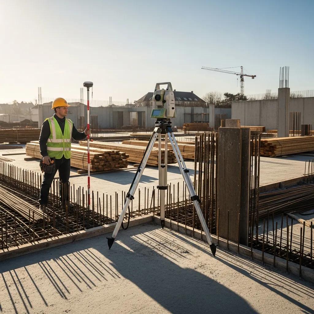
Robotic Total Station layout uses a motorized total station to locate and stake coordinates directly from digital models, enabling placement accuracy down to millimeter tolerances. The system pairs precise angle and distance measurements with automated stakeout and verification routines, producing repeatable results with a single operator and removing common transcription errors. Primary benefits include tighter positional control for anchor bolts and facade control points, faster stakeout cycles for interiors, and verifiable logs that support QA/QC sign-offs. That combination makes robotic layout ideal where tight tolerances and cumulative-error sensitivity matter—multi-floor MEP hangers and facade alignment, for example. The following paragraphs break down device roles, operational metrics, and a concise deliverables comparison to help owners and contractors set realistic performance expectations.
Typical Robotic Total Station deliverables include stakeout reports, verification point logs, and annotated as-built coordinates tied to model geometry. The comparison below helps teams weigh the trade-offs between speed, accuracy, and manpower.
Different layout deliverables map to distinct accuracy and operational expectations.
| Deliverable | Characteristic | Typical Metric |
|---|---|---|
| MEP layout points | Positional accuracy | ±5–15 mm |
| Anchor bolt verification | Tolerance reporting | ±3–10 mm |
| Overhead hanger layouts | Vertical/alignment control | ±5 mm vertical repeatability |
This table shows how deliverables translate into measurable tolerances and helps define acceptance criteria. The next subsection describes the Trimble Robotic Total Station and why it is widely used for these tasks.
What role does the Trimble Robotic Total Station play in precision layout?
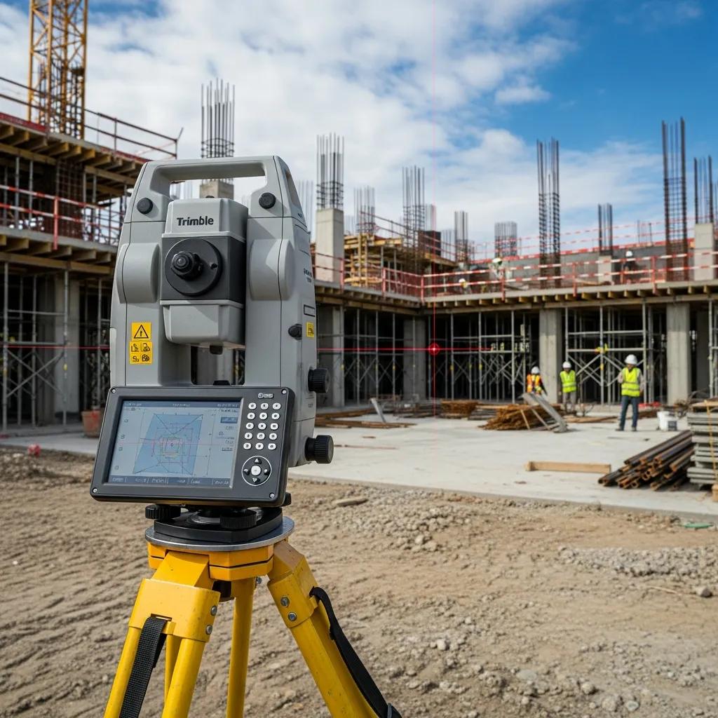
The Trimble Robotic Total Station delivers automated angle and distance measurement with integrated field software, enabling single-operator stakeout from BIM-derived coordinate sets. Device capabilities include automated tracking, remote targeting, and high-resolution encoders that achieve millimeter-level tolerances when properly calibrated and tied to control. Typical Trimble workflows pair the instrument with model exports and verification routines that log measured versus as-designed positions, creating traceable QA artifacts. Alt text recommendation: “Trimble robotic total station set on tripod for model-driven stakeout.” Knowing the Trimble’s precision and repeatability helps teams write meaningful tolerances into contracts and acceptance checklists, which leads into how robotic layout reduces errors and improves efficiency.
How does robotic layout reduce errors and speed work on complex projects?
Robotic layout eliminates many manual measurement handoffs by using direct coordinate inputs from the model, removing a common source of transcription mistakes between design and field teams. Key mechanisms include automated stakeout, immediate verification logging, and repeatable retrieval of control points that ensure consistent placement across trades and floors. Efficiency gains come from single-operator workflows, shorter setup times versus multi-person survey crews, and faster rework verification—translating into fewer labor hours per area. Many projects quantify reduced rework and faster milestone handoffs when coordinate-driven staking is enforced. Those efficiencies also create clearer feedback loops for model updates and fabrication readiness, which we explore next through BIM coordination and clash avoidance.
What advantages does BIM coordination bring to complex architectural work?
BIM coordination integrates discipline-specific models into a shared environment to find clashes, align system routing, and produce fabrication-ready geometry that respects field constraints and layout tolerances. The process centers on model federation, automated clash detection, and structured coordination meetings that turn model issues into tracked resolutions. Benefits include fewer in-field clashes, greater confidence in prefabrication, and the ability to generate digital twins for long-term asset management. These outcomes reduce schedule risk and lower downstream change orders by catching conflicts before installation. The next paragraphs explain clash workflows, the path to fabrication-ready models, and a short case snapshot that demonstrates measurable rework avoidance from BIM coordination.
BIM coordination workflows typically produce clash reports and issue-resolution logs that translate into hours saved on-site and percent reductions in rework. The table below maps common BIM deliverables to expected project outcomes so teams can prioritize coordination effort.
| BIM Deliverable | Attribute | Outcome |
|---|---|---|
| Clash detection report | Issues identified | Up to 70% of constructability issues caught pre-installation |
| Federated coordination model | Integrated geometry | Enables prefabrication and reduced shop adjustments |
| Issue tracker with resolutions | Action items closed | Shortens RFIs and reduces on-site change orders |
Use this mapping to write coordination deliverables and acceptance criteria into specifications. The next subsection explains how clash detection is executed and tracked in practice.
How does BIM coordination enable practical clash detection and resolution?
Clash detection uses rule-based tools to compare geometry from architectural, structural, and MEP models and flag spatial conflicts that breach clearance or routing rules. The workflow begins with model federation, proceeds with automated clash runs, and includes manual review to prioritize issues by severity and constructability impact. Resolution cycles live in issue trackers that assign responsibility, record design changes, and close items once verification is complete—creating auditable records for the project team. Common outcome metrics include the number of issues resolved before construction and hours of on-site rework avoided. Effective clash management reduces installation uncertainty and supports higher-fidelity fabrication models, which we cover next.
How does BIM integration support fabrication-ready models and digital twins?
BIM integration prepares models for fabrication by increasing LOD and LOI, embedding tolerance metadata, and producing shop drawings and CNC-ready geometry for off-site assembly. Refined models include part-level properties, connection details, and annotated tolerances that fabricators use to limit field modification. For digital twins, the same model data—aligned to asset IDs and as-built coordinates—forms the foundation for operations and maintenance after turnover. Recommended fabrication handoffs include annotated assembly files, plate drawings with hole patterns, and verification checklists that match field measurement records. These model-driven handoffs reduce on-site adjustments and improve alignment between design intent and installed assets, which is where VDC consulting coordinates the handoff.
As a credibility note, Conway Coordination and Layout Services (CCLS) has used BIM coordination to reduce fabrication rework on select projects by aligning model tolerances with field-verification workflows, improving prefabrication certainty and installation timelines.
For teams seeking the same results, CCLS combines BIM modeling and coordination with verification routines to close the gap between model and field.
How does VDC consulting streamline workflows for precision layout?
VDC consulting aligns digital models, schedules, and field verification so the digital plan translates into accurate, auditable field placement. The scope includes defining model standards, setting coordination cadences, and creating QA/QC templates that govern digital-to-field handoffs. Key elements are standardized model exchange formats, schedule-linked stakeout plans, and iterative constructability reviews that expose impossible conditions early. By optimizing these workflows, VDC reduces friction between design decisions and on-site execution, improves prefabrication readiness, and shortens approval loops for layout acceptance. The next paragraphs outline specific digital optimizations and risk-mitigation practices VDC consultants use to support precision outcomes.
VDC consulting delivers standardized workflows and checklists that convert model geometry into stakeout-ready coordinates and clear field verification steps. The list below shows practical digital workflow optimizations that directly improve field accuracy and reduce ambiguity.
- Standardized model exchanges with consistent naming conventions and coordinate references to eliminate translation errors.
- QA/QC checklists for stakeout and verification that ensure acceptance criteria are applied consistently.
- Prefabrication coordination protocols that tie shop drawings to model-level tolerances and field verification routines.
What digital workflow improvements does VDC consulting provide?
VDC consulting prescribes model exchange standards, version control practices, and verification checklists that translate into measurable field efficiency and clarity. Standardization reduces mismatched coordinate systems and ensures model exports include the metadata required for stakeout and prefabrication. QA/QC templates define verification thresholds, reporting formats, and acceptance signoffs so field measurement logs feed back into model updates without ambiguity. Prefab coordination links part-level tolerances to shop schedules, lowering the chance of mismatched assemblies on delivery. These optimizations shorten coordination cycles and support more reliable installation sequences, which connects directly to risk mitigation.
How does VDC consulting reduce risk on complex projects?
VDC reduces risk through virtual constructability reviews, schedule simulation, and contingency planning that reveal issues long before site work begins. Virtual reviews simulate installation sequences, highlight spatial constraints, and let multi-discipline teams iterate on routing solutions before fabrication. Schedule modeling aligns prefab deliveries with installation windows to avoid site congestion and provide buffer time for verification. Contingency planning defines fallback layouts and clear acceptance criteria to limit on-site indecision. These proactive measures cut downstream rework, compress RFIs, and protect critical-path milestones—preparing the ground for accurate layout execution supported by 3D scanning where needed.
What role do 3D scanning and point cloud integration play in architectural precision?
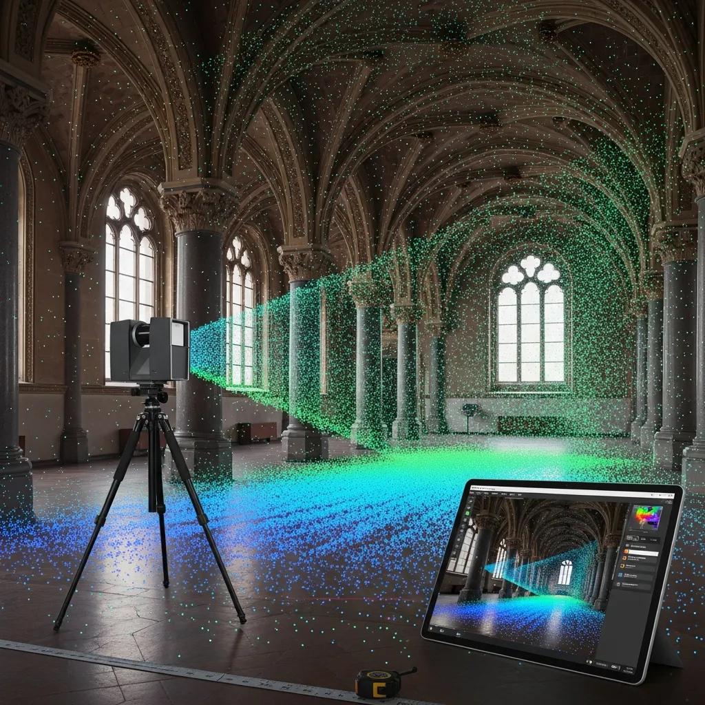
3D scanning captures high-density point clouds that document as-built conditions with sub-centimeter accuracy, giving an empirical basis for verification, retrofit design, and model registration. The workflow pairs laser scanning or structured-light hardware with registration and processing software to produce a unified dataset aligned to project control and BIM coordinates. Common applications include as-built capture for renovation, verification of installed conditions against design intent, and reference geometry for prefabricating retrofit elements. Integrating point clouds into BIM workflows reduces risk by exposing hidden interferences and enabling precise measurement for anchor-bolt placement, hanger routing, and facade repairs. The following subsections describe scanning for verification and point-cloud use in renovation workflows.
Here are three typical use cases where 3D scanning drives accurate outcomes.
- As-built documentation to confirm structural openings and service penetrations before cutting or installing new systems.
- Retrofit and renovation scanning to convert existing conditions into accurate BIM geometry for prefabrication.
- Model verification that compares installed coordinates against design tolerances for acceptance reporting.
These cases show how point cloud integration supports faster decisions and fewer costly on-site discoveries. The next subsection explains scanning workflows for layout verification.
How does 3D scanning capture as-built conditions for verification?
3D scanning uses terrestrial LiDAR or structured-light systems to record millions of spatial points, which are then registered to control and processed into a coordinated point cloud. Registration aligns individual scans into a common coordinate system and tolerance checks compare cloud-derived geometry to the model to reveal deviations. Verification workflows typically include a sampling plan, target-based control checks, and automated deviation reports that quantify where installed elements differ from design. That rigorous verification prevents destructive rework by validating clearances and anchor locations before fabrication or installation. Properly executed scanning becomes the empirical anchor for model adjustments and field stakeout refinement.
How is point cloud rendering used in renovation and retrofit projects?
Point cloud rendering converts raw scan data into readable formats and simplified geometry that designers and fabricators can use for decision-making. Converting point clouds to BIM geometry creates a reliable baseline for clash detection, prefabrication, and fabrication drawings in retrofit scenarios. Renderings and simplified surfaces also help stakeholders visualize constraints and approve interventions without repeated site visits. Typical deliverables include registered point clouds, annotated deviation maps, and LOD-specified geometry for fabrication—deliverables that reduce surprises during retrofit installation and improve coordination between trade contractors. These outputs feed directly into the industry-specific layout needs described next.
How do precision layout services tackle industry-specific challenges?
Precision layout services adapt methods and tolerances to sector-specific needs—clinical clearances in healthcare, equipment anchoring in industrial facilities, and facade alignment in commercial projects. We tailor verification thresholds, coordination cadence, and deliverable formats to compliance regimes, operational demands, and maintenance expectations. For example, healthcare projects prioritize redundant MEP routing and strict clearances around sterile zones, while industrial facilities require heavy-tolerance anchor-bolt verification for rotating equipment. Aligning layout strategies with industry constraints reduces operational risk and ensures installed systems meet both design intent and functional requirements. The following subsections detail healthcare tolerances and industrial/commercial applications.
To illustrate how services map to sector needs, consider these common constraints and how precision layout addresses them.
- Healthcare: Critical clearance zones, redundant MEP pathways, and as-built verification to support clinical workflows.
- Industrial: Equipment anchor verification, load-path alignment, and exact foundation geometry for heavy machinery.
- Commercial: Facade alignment, curtainwall tolerances, and consistent floor-to-floor datum transfer.
Customizing layout methods for these constraints ensures installations support operations and maintenance rather than creating downstream obstacles. The next subsection focuses on healthcare-specific tolerances.
What precision layout requirements apply to healthcare construction?
Healthcare construction demands strict coordination of clearances, redundant mechanical pathways, and pinpoint locational accuracy for critical equipment to protect clinical workflows and patient safety. Typical thresholds include tighter-than-normal tolerances around penetrations and headwalls, precise riser locations for MEP distribution, and documented verification of redundancy for critical services. Coordination priorities emphasize minimizing shutdown windows and ensuring layout sequences do not compromise sterile zones or critical uptime. Detailed verification deliverables—annotated as-built coordinates and acceptance logs—support regulatory review and operational handoff. These healthcare requirements show why integrated workflows combining robotic layout, BIM coordination, and scanning are essential for clinical projects.
How is precision layout applied in industrial and commercial projects?
In industrial and commercial settings, precision layout focuses on anchor-bolt verification, equipment placement relative to production flows, and facade alignment for performance and aesthetics. Anchor-bolt verification uses direct coordinate measurements and plate templates so heavy equipment installs without field modification, avoiding costly shutdowns for realignment. Facade and structural coordination rely on tight control points and verified datum transfer between floors to maintain continuous envelope alignment. These practices reduce operational interruptions, lower maintenance complexity, and preserve design intent—making precision layout a strategic investment, not an optional add-on.
What are the key benefits of partnering with expert precision layout providers like CCLS?
Working with an expert precision layout provider delivers measurable benefits: lower construction costs through reduced rework, better schedule adherence via predictable stakeout and verification, and reduced operational risk through robust QA/QC documentation. Expert teams integrate surveying technology, BIM coordination, and verification reporting into a cohesive workflow that ties acceptance criteria to deliverables. Clients receive traceable records—stakeout logs, as-built coordinate sets, and clash-resolution histories—that help avoid disputes and smooth turnover to operations. The table below summarizes service-to-benefit relationships and points to the next step for teams that need a precision-focused partner.
| Service | Typical Issue Addressed | Typical Benefit/Metric |
|---|---|---|
| Robotic Total Station Layout | Inaccurate anchor/fixture placement | Reduced rework; positional accuracy within millimeters |
| 3D Scanning & Point Cloud Integration | Unknown as-built conditions | Fewer change orders; verified geometry for prefabrication |
| VDC Consulting & BIM Coordination | Design-to-field misalignment | Shorter RFIs and reduced schedule impact; improved fabrication readiness |
This table helps project teams quantify which services to specify and the likely gains. For decision-makers ready to apply these methods, here’s how to start.
If your team needs a consultation or a precision layout quote, contact Conway Coordination and Layout Services (CCLS) to request a tailored review of layout tolerances, verification workflows, and coordination deliverables. CCLS centers its offering on core value propositions—Precision You Can Trust, Seamless Coordination, Proven Expertise, and Adaptability & Reliability—across Robotic Total Station Layout, VDC Consulting, BIM Modeling and Coordination, and 3D Scanning and Point Cloud Integration. Requesting a focused review opens a technical conversation that maps tolerances to deliverables and clarifies acceptance criteria without committing to services up front.
How does precision layout lower construction costs and limit delays?
Precision layout lowers costs by preventing rework, enabling prefabrication, and shortening the time trades spend resolving field conflicts—reducing labor and material waste. Mechanisms include accurate stakeout that avoids misaligned anchors, early clash detection that prevents late design changes, and verification reporting that speeds acceptance and turnover. Timeline improvements are tangible: fewer RFIs and faster verification cycles accelerate handoffs between trades, conserving schedule float and protecting milestone dates. Many projects report measurable reductions in on-site rework hours and associated cost savings when model-driven layout and verification are used from early stages.
Why is expert coordination essential for architectural layout accuracy?
Expert coordination translates across disciplines, enforces model standards, and manages the feedback loop between field verification and model updates so accuracy holds across project stages. Coordination tasks include assigning model owners, enforcing naming and coordinate systems, scheduling clash runs, and validating verification deliverables against acceptance thresholds. Without that orchestration, device outputs and software data can remain siloed and misinterpreted. Experienced coordinators make robotic layout, scanning, and BIM deliverables into a cohesive, auditable package that supports predictable installation and reliable long-term assets.
This article has outlined methods, workflows, comparison tables, and practical lists to guide teams in specifying precision layout services for complex designs. Applying integrated approaches—robotic total station staking, model-driven BIM coordination, VDC-aligned workflows, and targeted 3D scanning—delivers predictable, verifiable outcomes that reduce cost and preserve operational performance on complex construction projects.
Frequently Asked Questions
What types of projects benefit most from precision layout services?
Precision layout services provide the most value on complex projects in healthcare, industrial, and commercial construction. Healthcare needs strict tolerances and clearances for patient safety and workflow; industrial projects require precise anchors and load-path control for heavy machinery; commercial work focuses on facade alignment and envelope performance. Tailoring methods to each sector helps ensure installations meet design intent and operational needs.
How can precision layout services shorten project timelines?
Precision layout shortens timelines by reducing rework and the time trades spend resolving field conflicts. Advanced tools—Robotic Total Stations, BIM coordination, and 3D scanning—enable accurate stakeouts and early clash detection, speeding verification cycles and smoothing handoffs between trades. The net result is fewer delays, fewer RFIs, and better protection of critical-path dates.
What role does quality assurance play in precision layout?
QA is central to precision layout. Verification reporting documents the accuracy of installations versus design, and regular audits of layout practices ensure consistency. QA protocols help teams catch and fix issues early, reducing costly rework and ensuring the final installation aligns with design intent and operational requirements—improving reliability and client confidence.
How does technology integration improve precision layout outcomes?
Integrating BIM, Robotic Total Stations, and 3D scanning streamlines workflows and raises accuracy. These tools enable real-time data sharing and collaboration, reducing errors from miscommunication. Automated processes—clash detection and verification logging—ensure installations follow tight specifications and produce traceable records that support QA and accountability.
What common challenges arise in precision layout projects?
Common challenges include complex geometries, multidisciplinary coordination, and strict industry standards. Site variability and the need for quick adjustments can complicate execution, and communication gaps between design and field teams often create misalignment. Addressing these issues requires robust coordination strategies, advanced technology, and clear communication throughout the project lifecycle.
How can clients judge the effectiveness of precision layout services?
Clients can evaluate effectiveness using KPIs such as rework rates, schedule adherence, and installation accuracy. Regularly reviewing verification reports, clash detection outcomes, and stakeholder feedback reveals process quality. Tracking change orders and RFIs also indicates coordination efficiency. These metrics help determine the value provided and inform future project decisions.
Conclusion
Partnering with precision layout specialists like Conway Coordination and Layout Services (CCLS) delivers measurable benefits: lower construction costs through reduced rework, improved schedule performance, and decreased operational risk thanks to thorough QA/QC documentation. By integrating Robotic Total Stations, BIM coordination, VDC consulting, and 3D scanning, teams achieve higher accuracy and smoother turnovers to operations. If you’re ready to elevate your next project’s layout certainty, contact CCLS to explore tailored precision layout solutions.