Accurate Anchor Bolt Verification for Structural Integrity: Precision Layout & Inspection Services
Accurate anchor bolt verification confirms anchor bolts are located, spaced, and embedded to the design coordinates and tolerances required for reliable load transfer to the foundation. This piece describes how precision layout and verification—backed by modern surveying instruments and coordinated digital workflows—protect structural integrity, cut costly rework, and support code compliance. You’ll find clear explanations of why bolt accuracy matters, the field workflows used to reach millimeter-level results, how BIM and VDC reduce installation errors, applicable standards and tolerances, common installation failures and fixes, plus real-world case outcomes. By emphasizing survey control, model alignment, post-pour as-built surveys, and QA checks, teams can avoid schedule slip and expensive corrective work. The sections that follow break down technical methods, provide practical lists for field crews, and show how focused layout and verification deliver measurable project benefits.
Why is Accurate Anchor Bolt Verification Essential for Structural Integrity?
Verification proves anchors are where the design requires them to be. When bolt locations match the model, load paths are predictable and base plates and members align correctly. Because bolts carry shear and tension between the superstructure and foundation, even small placement errors can force shimming, introduce eccentric loads, or require retrofit fixes that weaken connections. Verification also reduces schedule risk by catching deviations before steel erection and avoiding expensive re-drilling, epoxy anchors, or engineered remedies. The short list below captures the core benefits and sets the stage for the technical steps that follow.
Anchor bolt verification delivers three primary benefits:
- Safety and load continuity: Correct bolt placement preserves designed load paths and prevents unexpected stress concentrations.
- Code compliance and inspection readiness: Documented verification shows conformance with structural specs and speeds engineer and authority acceptance.
- Cost and schedule avoidance: Early detection of errors prevents rework, erection delays, and contractor claims.
These benefits lead directly into the mechanics of how placement accuracy preserves stability and what risks arise when bolts are out of position. The next section explains load transfer mechanics and the link between bolt position and structural behavior.
How Does Anchor Bolt Accuracy Ensure Structural Stability and Safety?
When anchor bolts are placed per design, columns and base plates sit within the intended alignment and axial, shear, and moment loads distribute as expected. Misplaced bolts introduce eccentricities that cause unplanned bending and stress concentrations. Field-verified coordinates reduce the need for shims and avoid retrofit solutions that can compromise connection performance. In practice, holding bolt pattern, elevation, and spacing to millimeter tolerances improves fit-up during erection and lowers the risk of dynamic effects from misaligned connections. These issues matter most under seismic, wind, or heavy-service loading, where small geometric deviations can amplify internal forces and shorten fatigue life. That’s why verification is essential on high-stakes structural systems.
What Are the Risks and Costs of Inaccurate Anchor Bolt Placement?
Incorrect anchor placement typically creates rework, schedule disruptions, and potential vulnerability when fixes are required after concrete cure or during steel erection. Common remediation—re-drilling, epoxy anchors, or redesigning base plates—carries direct labor and material costs plus indirect losses from delayed trades and inspections. These mistakes can also spark contractual disputes and require extra supervision. In many cases, modest spending on pre-pour layout and post-pour verification saves money by avoiding high-cost corrective actions and keeping erection on schedule. The next section shows how robotic total stations and contemporary workflows deliver the millimeter-level accuracy needed to prevent these risks.
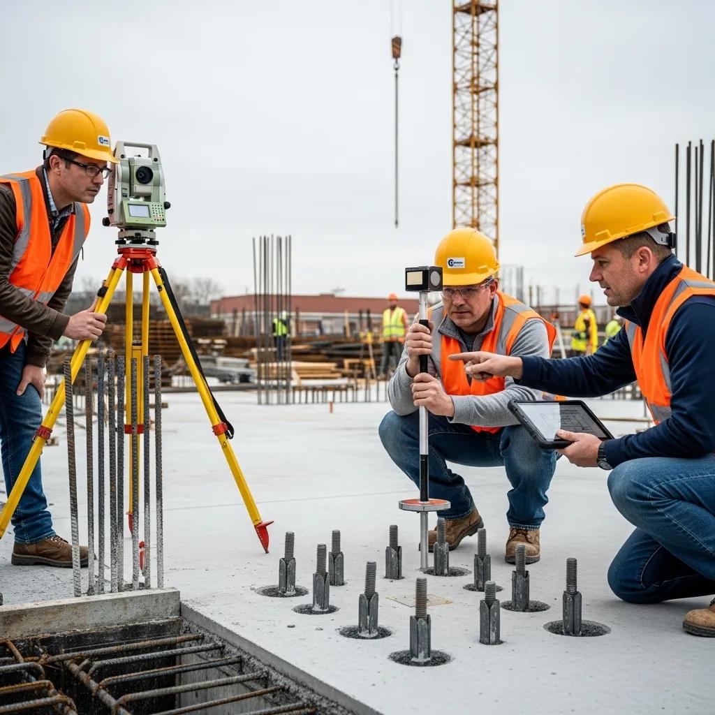
How Does CCLS Use Robotic Total Station Technology for Precision Anchor Bolt Layout?
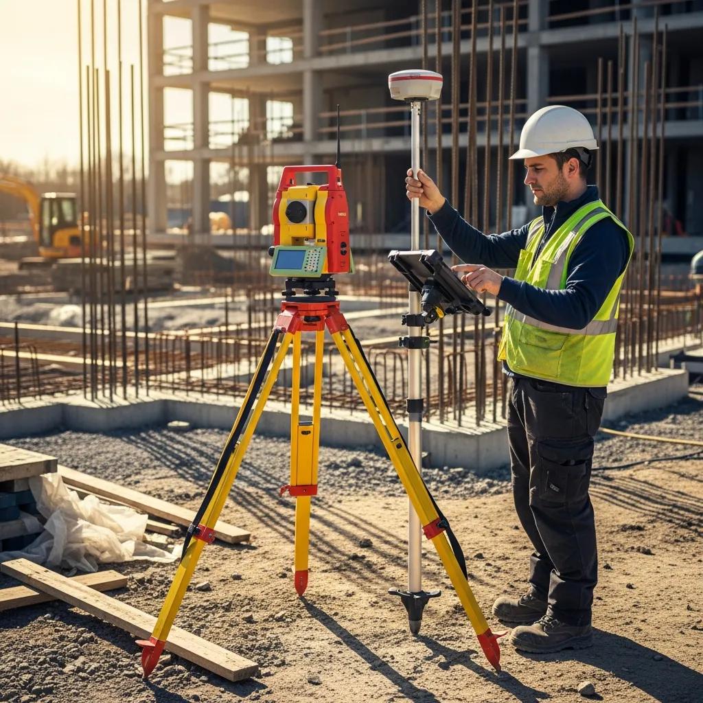
Robotic total station workflows combine stable site control, precise instrument setup, and digital stakeout procedures to place and verify anchor bolts within millimeter tolerances. The process starts by building a reliable control network, registering the instrument to model coordinates, staking out embedment templates before pour, and then performing post-pour as-built surveys to record actual bolt positions. That workflow produces annotated plans, point files, and QA reports that demonstrate compliance and support immediate corrective decisions. Below is the field workflow our teams follow to ensure accuracy and traceability.
- Establish control and register model coordinates: Tie the total station to project control and align to BIM coordinates.
- Pre-pour layout and verification: Stake out embedment templates and verify offsets before concrete placement.
- Post-pour as-built survey: Capture actual bolt locations, elevations, and spacing immediately after cure for QA.
- Deliverables and coordination: Produce annotated drawings, CSV/point files, and as-built documentation for design review.
When instruments are calibrated and registration is correct, this workflow achieves millimeter-level results. The table below summarizes common instrument outputs and typical accuracy characteristics from robotic total station workflows used for precision anchor bolt layout.
Robotic total station deliverables and accuracy overview:
| Instrument / Output | Characteristic | Typical Value |
|---|---|---|
| Robotic Total Station | Positional accuracy | ±2–10 mm (project-dependent) |
| Output File | Data formats | Point file (CSV), annotated plan (PDF), CAD/BIM-ready CSV |
| Field Deliverable | Survey report | As-built coordinates, elevation, discrepancy log |
These deliverables let teams make fast, informed decisions and form the basis for model reconciliation and erection planning. The next subsection highlights the practical advantages of millimeter-level accuracy for field operations.
What Are the Benefits of Millimeter-Level Accuracy in Anchor Bolt Verification?
Tighter accuracy reduces the need for base plate shims, speeds steel erection, and minimizes field changes that drive cost and delay. Precisely placed bolts improve fit-up certainty, shorten inspection cycles, and reduce downtime for trades waiting on structural fit checks. Projects with tight tolerances—precast connections, heavy machinery foundations, or process supports—see immediate benefits because fewer adjustments are required during erection. The result is a smoother handoff between concrete crews and steel erectors, shorter crane and labor mobilization windows, and higher first-time acceptance rates from engineers. Those outcomes directly support project efficiency and owner satisfaction when paired with verified QA deliverables.
How Does Real-Time Data Capture Enhance Post-Pour Anchor Bolt Surveys?
Real-time data capture connects field measurements directly to stakeholders, enabling immediate quality checks, faster model updates, and auditable as-built records for downstream teams. When survey points flow from the total station into cloud or BIM platforms, engineers can quickly assess discrepancies and authorize mitigations before heavy trades proceed. This shortens feedback loops between field and office, reduces ambiguity during inspections, and creates traceable records that prove compliance. Rapid capture also supports on-the-spot decisions—accepting minor deviations or scheduling remedial work—that protect schedule float. The next section covers how digital model integration reduces installation errors before they reach the field.
How Does BIM and VDC Integration Improve Foundation Anchor Bolt Accuracy?

BIM and VDC integration improve anchor bolt accuracy by aligning the digital model to site control, enabling clash detection, and coordinating sequencing so embedded items and anchor layouts don’t conflict during construction. Model-driven layout ensures stakeout coordinates reflect design intent and that changes propagate to layout teams quickly. Feeding survey points and as-built data back into the model creates a verified source of truth for tolerance checks. Compared with paper drawings and manual transfers, BIM-enabled coordination cuts errors from misinterpretation and asynchronous updates. The checklist below outlines practical steps teams should follow for model-to-field alignment.
- Register model coordinates to site control: Confirm the transformation between model and survey control.
- Establish verification checkpoints: Place survey points to validate registration accuracy.
- Update model with as-built survey data: Feed measured points back into BIM for reconciliation.
This checklist reduces translation errors and supports proactive clash detection workflows. The next subsection explains verification checkpoints and how they keep alignment accurate during layout.
What Role Does Digital Model Alignment Play in Anchor Bolt Coordination?
Digital model alignment guarantees the coordinates used in the field share the same coordinate system, units, and origin as the design model—preventing offsets that cause misplacement. Alignment includes control tie-in, verification checkpoints, and periodic rechecks when site activity could affect control. Routine checkpoints—measured and compared to model coordinates—confirm the total station and model remain within acceptable tolerance before and during layout. Those checks also reveal drift or setup issues early. Documenting alignment checks maintains traceability and gives engineers and contractors confidence that layout follows design intent.
How Does Clash Detection Prevent Anchor Bolt Installation Errors?
Clash detection analyzes spatial conflicts in the model, identifying embedded items, mechanical penetrations, and structural interfaces that could interfere with anchor bolt locations before concrete is poured. Catching clashes early lets teams resolve conflicts via model updates, detail changes, or relocation strategies that avoid field rework. For example, spotting an embed plate clash with conduit routing prior to layout prevents costly post-pour remediation or bolt relocation. Documented, coordinated resolutions sent to layout crews ensure the final bolt pattern satisfies both structural needs and embedded conditions. In short, clash detection turns many on-site surprises into planned, documented changes that protect schedule and integrity.
What Are the Industry Standards and Tolerances for Anchor Bolt Installation?
Standards like AISC and ACI give guidance on anchor bolt positional tolerances, embedment depth, and acceptance criteria. Verification services translate those requirements into measurable field checks and reports. Typical tolerance bands cover positional offset, verticality, and embedment depth; these limits determine whether bolts are acceptable or need remediation. Verification maps measured coordinates to code limits and produces compliance summaries designers can accept or use to authorize fixes. The table below summarizes common standard-to-tolerance relationships for field teams and QA reviewers.
Standards and typical anchor bolt tolerance mapping:
| Standard | Specification | Typical Tolerance |
|---|---|---|
| AISC 360 | Positional tolerance for anchors | ±10–25 mm (project-specific) |
| ACI 318 (anchor guidance) | Embedment depth acceptance | Per engineer design; check depth within ±5–10 mm |
| Code Applicability | Use case | Steel-to-concrete connections; check per contract documents |
This mapping is a practical starting point for interpreting design requirements. Actual tolerances should always come from contract documents and engineer directives. The next subsection describes how verification workflows document compliance and support acceptance.
How Does CCLS Ensure Compliance with AISC 360 and ACI Guidelines?
CCLS follows a measurement and reporting workflow that ties field-measured coordinates to the referenced standards, checking positional offsets, embedment depths, and verticality against specified acceptance criteria. Our QA process includes instrument calibration, multi-pass verification, and annotated as-built deliverables that call out deviations needing engineer review. Standardized documentation summarizes measurements, tolerance checks, and recommended corrective actions so designers and contractors can make informed decisions. Traceable measurement records aligned to standards help speed acceptance and reduce disputes over whether anchor placements meet contractual requirements.
What Quality Control Protocols Are Used in Structural Bolt Verification?
QC for bolt verification includes instrument calibration checks, redundant control points, independent spot checks, and multi-stage verification before and after concrete placement. Checklists govern setup, registration, and data capture. Independent verification—either by a second surveyor or cross-check points—helps catch human or instrument error. Documentation is kept in standard formats that list control data, measurement uncertainty, and discrepancy logs for engineer review. These protocols ensure verification results are reliable and corrective actions rest on documented evidence rather than subjective judgment.
Which Common Anchor Bolt Errors Can Be Prevented Through Professional Verification?
Professional verification prevents frequent errors like plan misalignment, incorrect embedment depth, wrong spacing, and clashes with embedded items. Targeted detection methods and remediation strategies address each issue before it escalates. Verification services use layout templates, depth checks, and immediate post-pour surveys so teams can correct mistakes early or document deviations for engineered remedies. The table below maps common error types to detection methods and typical correction strategies—a quick field reference for QA managers and crews.
Common anchor bolt errors, detection, and mitigation:
| Error Type | Detection Method | Correction / Mitigation |
|---|---|---|
| Misalignment (plan) | Surveyed coordinates vs. model | Re-layout prior to pour or use engineered slots/epoxy anchors |
| Incorrect embedment depth | Depth gauges, post-pour elevation checks | Adjust plate detail or use shim/epoxy anchor where allowed |
| Clash with embedded items | BIM clash detection, pre-pour verification | Relocate embed or coordinate conduit/run changes |
This reference helps teams prioritize inspections and select corrective approaches aligned with engineer guidance. The following subsections detail detection techniques and practical fixes for material and installation issues.
How Are Misalignment and Incorrect Embedment Depth Detected and Corrected?
Misalignment is caught by comparing measured anchor coordinates to the design model with survey instruments or templates. Embedment depth is verified with depth gauges and vertical control checks after the pour. Corrective actions depend on severity: small horizontal offsets may be tolerable or corrected with plate shims; larger deviations often require engineered fixes such as re-drilling with epoxy anchors or redesigning the base plate connection. Decisions weigh structural implications, code requirements, and constructability. Verification reports provide the data engineers need to approve the least-impact remediation. Quick detection enables earlier, less invasive fixes and keeps steel erection on schedule.
What Solutions Address Material Selection and Installation Issues?
Good material choices and disciplined installation prevent long-term failures. Specify corrosion-resistant anchors where required, verify embedment sleeves, and follow manufacturer installation instructions. Use anchors rated for the expected load type (tension vs. shear) and document batch/lot information when specs require it. Qualified installers and field supervision reduce variability, and pre-pour verification of templates and embed locations prevents common mistakes. These proactive steps minimize corrective actions and preserve the design intent for long-term durability.
Before showing project-level proof, note how professional verification workflows convert problem identification into actionable engineering decisions. The case studies below demonstrate measurable results from precision verification work.
What Case Studies Demonstrate CCLS’s Expertise in Accurate Anchor Bolt Verification?
Case studies show how precise layout and verification avoided costly rework and kept steel erection on schedule in complex projects. One representative engagement—“Flawless Anchor Bolt Verification – Confidential Pharmaceutical Facility, Western NC”—demanded tight positional control, close coordination with structural engineers, and careful handling of deliverables. The project used model alignment, robotic total station layout, and post-pour surveys to document compliance and enable uninterrupted erection sequencing. The short case narrative below summarizes the technical approach and quantifiable benefits achieved by the verification workflow.
How Was Flawless Anchor Bolt Verification Achieved at a Pharmaceutical Facility?
On the confidential pharmaceutical project, the team established robust control, tied the BIM model to survey coordinates, and used a Trimble Robotic Total Station for pre-pour and post-pour verification of embed layouts. Multi-pass checks and immediate as-built capture allowed quick identification and correction of deviations within allowable tolerances. Deliverables included annotated plans and point files for the structural engineer’s sign-off. The workflow emphasized precision, traceability, and minimal impact to adjacent trades—critical in a regulated facility—and produced a documented record accepted by the design team that let erection proceed without remedial delays.
For teams seeking similar results, Conway Coordination and Layout Services (CCLS) provides Robotic Total Station layout and focused anchor bolt verification with an emphasis on precision, efficiency, and predictable outcomes. A consultation with Nathan Conway will clarify how these processes apply to your project constraints and acceptance criteria.
What Measurable Benefits Resulted from CCLS’s Precision Services?
Typical outcomes from precision verification include higher first-pass acceptance rates, less time spent on field modifications, and faster steel erection cycles—translating to direct schedule and cost savings. On comparable projects, teams reported fewer on-site corrective actions, reduced crane idle time, and quicker inspector sign-off thanks to clear as-built documentation. Useful KPIs include reductions in rework hours, increases in on-time erection milestones, and documented acceptance rates for anchor layouts. These metrics demonstrate the return on investment of early, accurate verification and validate the use of advanced surveying technologies on structural projects.
When teams must demonstrate compliance and keep tight schedules, precision verification delivers measurable improvements that preserve momentum and reduce disputes over installation quality. As a next step, consider model-driven layouts and robotic total station verification to capture these benefits.
Frequently Asked Questions
What types of projects benefit most from anchor bolt verification?
Projects with heavy structural loads—high-rises, bridges, industrial facilities—benefit most because precise load transfer is critical. Facilities with strict regulatory or process requirements, like pharmaceutical plants and data centers, also gain from verification to meet compliance and avoid costly disruption. In short, any project where anchor accuracy affects safety, function, or schedule should include verification.
How often should anchor bolt verification be performed during a project?
Verification should happen at multiple stages. Pre-pour verification ensures layouts match design before concrete placement. Post-pour surveys confirm actual bolt positions after cure. Additional periodic checks during construction help catch drift or control issues early. Staged verification reduces risk and keeps projects on schedule.
What tools are commonly used for anchor bolt verification?
Common tools include robotic total stations, laser scanners, and digital levels. Robotic total stations deliver high positional precision for stakeout and as-built capture. Laser scanners gather rapid 3D data for model comparisons. Digital levels verify verticality and embedment elevations. Together, they support accurate measurements and traceable records.
Can anchor bolt verification help in reducing construction delays?
Yes. Verification identifies issues before they block erection, allowing timely corrections that avoid rework and schedule knock-on effects. Early detection keeps steel erection and downstream trades moving and reduces costly delays caused by misaligned anchors.
What are the consequences of neglecting anchor bolt verification?
Neglect can lead to misaligned anchors, eccentric loads, and unexpected stress concentrations that compromise structural performance. Fixes after cure—re-drilling, epoxy anchors, or redesign—are costly and time-consuming. Noncompliance with standards can also trigger disputes and reputational risk. Verification is a practical way to avoid these outcomes.
How does anchor bolt verification contribute to overall project quality?
Verification ensures structural elements are installed as designed, maintaining intended load paths and preventing stress concentrations. Thorough verification produces documentation that supports code compliance and inspector acceptance. By reducing errors and rework, verification raises overall project quality, safety, and durability.
Conclusion
Accurate anchor bolt verification is a straightforward investment in structural integrity, safety, and schedule certainty. Using calibrated instruments, model-led workflows, and disciplined QA checks, teams can reduce rework, speed erection, and provide the documentation engineers and owners require. If you want reliable, measurable results on your next project, contact us to discuss how our specialized verification services can help.