Automated Construction Layout Services in Atlanta, GA: Precision Solutions with Robotic Technology
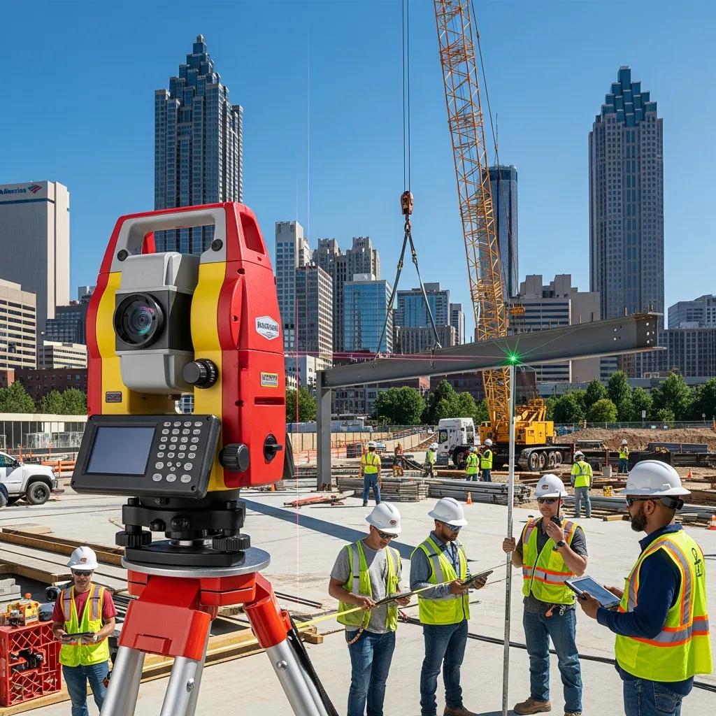
Automated construction layout uses robotic positioning systems, model-driven coordinates, and reality-capture workflows to place building elements with millimeter-level precision—anchored by Robotic Total Station technology. This guide shows how automated layout cuts rework, tightens trade coordination, and keeps schedules on track for Atlanta projects by linking BIM, VDC, and 3D scanning to field execution. You’ll get a clear picture of what automated layout looks like in practice, how Trimble Robotic Total Station workflows improve accuracy, which core services drive measurable results, and how point-cloud integration prevents common coordination issues. We also call out regional considerations for Atlanta teams and explain how an experienced provider blends technology and process to deliver reliable field outcomes. By the end, you’ll understand trade-specific uses, expected tolerances, efficiency gains, and how to engage a precision layout partner for complex MEP, structural, or renovation work in the Atlanta market.
What Are Automated Construction Layout Services and Their Benefits in Atlanta?
Automated construction layout ties digital models to survey-grade hardware and coordinated field workflows so model coordinates are placed directly on-site as control points. In practice, BIM coordinates are imported into a Robotic Total Station or similar robotic platform, which then marks points on slabs, walls, or overhead systems with repeatable accuracy and far fewer manual transcription errors. For Atlanta projects—where sites are tight and MEP scopes are dense—the main advantages are greater precision, faster field work, less rework, and more predictable schedules. Understanding these benefits helps project teams evaluate automated layout as a practical risk-reduction and productivity tool across design-bid-build, design-build, and renovation deliveries.
Automated layout delivers four principal benefits for regional projects:
- Precision Placement: Millimeter-level layout reduces tolerance failures and fit-up problems during assembly.
- Reduced Rework: Fewer positional errors on the first pass cut labor and material waste.
- Faster Field Execution: Remote control and direct coordinate import shorten layout cycles.
- Improved Coordination: Model-driven points streamline trade sequencing and prefabrication readiness.
Those advantages translate into measurable project improvements. Next we explain how Robotic Total Station hardware delivers that accuracy in the field.
Introductory comparison of core automated layout technologies and their primary benefits.
| Technology | Key Attribute | Primary Benefit |
|---|---|---|
| Robotic Total Station | Remote-target positioning and model import | Millimeter-level layout accuracy |
| BIM Coordination | Federated model and clash detection | Reduced field clashes and RFIs |
| VDC Consulting | Workflow sequencing and model validation | Improved constructability and scheduling |
| 3D Laser Scanning | Point-cloud capture of existing conditions | Accurate as-built baselines for renovation work |
How Does Robotic Total Station Technology Enhance Construction Accuracy?
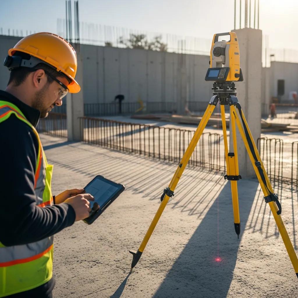
A Robotic Total Station combines automated target tracking, high-resolution angular measurement, and direct BIM coordinate import to perform repeatable, documented layout. The instrument locks onto prisms or reflective targets and follows them while an operator—or a remote system—places model coordinates as points, lines, or datums on the structure. Because coordinates flow directly from the model to the device, manual transfer errors that cause misalignment are largely eliminated. In real-world conditions, structural and MEP layout tolerances typically fall within a few millimeters to low centimeters depending on site constraints—enough to significantly reduce fit-up issues and on-site rework. Knowing how the instrument operates clarifies where time and quality improvements come from on active schedules.
What Efficiency Gains Do Automated Layout Services Provide to Atlanta Projects?
Automated layout shortens staking, hanger placement, and anchor verification by removing repetitive manual measures and enabling remote operation—clear wins for schedule performance. Teams using automated workflows report faster layout cycles and lower rework rates because model points convert directly to field marks, eliminating repeated re-checks and improvisation that stall progress. That reliability speeds trade coordination: prefabrication and sequencing depend on stable control points, allowing off-site fabrication with greater confidence and fewer change orders. On compressed schedules—multi-story core builds or rapid renovations—those time savings translate to cost avoidance and improved float management. The next section shows how experienced providers roll these technologies into Atlanta workflows.
How Does Conway Coordination and Layout Services Lead in Atlanta's Automated Layout Market?
Conway Coordination and Layout Services (CCLS) focuses on bringing Robotic Total Station workflows together with VDC, BIM coordination, and 3D scanning to deliver precise layout across the Southeast, with deep service coverage in Atlanta. Our capabilities include Trimble Robotic Total Station deployments, model-driven layout processes, and reality-capture verification—a technology stack built to support accurate field execution and clean digital handoffs. We emphasize reliability, practical technology use, and a proven regional track record—qualities that help general contractors and trade partners reduce layout risk and move installations more smoothly. For teams evaluating providers, CCLS offers consultation-led engagements that align layout deliverables with coordination schedules and prefabrication milestones to maximize constructability.
Conway’s approach pairs field-proven robotic hardware with disciplined BIM and VDC practices so layout deliverables are both accurate and actionable. That integration reduces RFIs and on-site delays because model points, clash reports, and control checks are validated before crews mobilize. The following sections explain how our institutional experience and Trimble-specific methods apply to Atlanta projects that require precision and timely delivery.
What Unique Advantages Does CCLS Offer with Over 20 Years of Expertise?
With two decades of regional experience, CCLS anticipates constructability challenges, tightens trade sequencing, and enforces quality controls often missed during early coordination. That institutional knowledge shows up as focused pre-layout audits, practical sequencing recommendations for MEP and structural teams, and hands-on problem solving that keeps work moving. Our familiarity with Southeastern project constraints—tight urban sites, phased renovations, and dense MEP networks—lets us adapt workflows to minimize schedule disruption. The result is fewer surprises during installation and a smoother move from design models to field layout, improving predictability for contractors and owners alike.
How Does CCLS Integrate Trimble Technology for Precision Layout?
We use Trimble Robotic Total Station features—remote control, automated targeting, and data import/export—to sync model coordinates with field execution through repeatable, documented workflows. Our typical sequence includes a model audit, coordinate export to the instrument, staged layout passes for control and punch-walk verification, and post-layout scanning or verification to confirm installed positions. Data exchanges between Trimble systems and BIM/VDC environments use standard coordinate formats and CSV exports so everyone references the same control. By sequencing layout around prefabrication milestones and verification checkpoints, the Trimble-enabled workflow reduces rework and provides QA/QC that supports downstream trades. This technical integration is core to the service suite we deliver in Atlanta.
What Are the Core Automated Layout Services Offered in Atlanta?
Our core automated layout services translate model data into field-ready control and verification deliverables across trades and project types. Typical offerings include Robotic Total Station layout for structural grids, MEP hanger and sleeve placement, anchor bolt verification, as-built capture with 3D scanning, and VDC consulting for coordination and sequencing. Each service is designed to reduce positional error, speed installation, and supply documentation that supports QA/QC and prefabrication decisions. Knowing how these services apply helps teams choose the right mix for their tolerance and schedule needs.
Primary services and typical applications include:
- Robotic Total Station Layout: Accurate grid and anchor-point placement driven by model coordinates.
- MEP Layout & Hanger Placement: Precise positioning for sleeves, hangers, and ceiling systems to cut field adjustments.
- Anchor Bolt Verification: Field confirmation against design coordinates to ensure foundation-to-superstructure fit.
- 3D Scanning & As-Built Capture: Point-cloud capture to establish renovation baselines and verify installs.
- VDC Consulting: Model audits, clash resolution, and sequencing to align field work with prefabrication.
These service categories map directly to measurable outcomes—reduced rework and tighter tolerance control—summarized in the table below.
| Service | Application | Typical Outcome / Metric |
|---|---|---|
| Robotic Total Station Layout | Structural grid and column layout | ±5–15 mm placement accuracy |
| MEP Layout & Hangers | Ductwork, piping, ceiling systems | 30–50% reduction in field adjustments |
| Anchor Bolt Verification | Foundations and baseplate alignment | Early detection of misalignment before erection |
| 3D Scanning | Renovation baselines and QA/QC | High-fidelity point cloud for model reconciliation |
How Is Robotic Total Station Layout Applied to MEP, Structural, and Anchor Bolt Projects?
Robotic Total Station layout adapts to trade tolerances by converting model coordinates into on-deck or overhead markups that guide installation with known accuracy. For MEP, coordination points for hangers, sleeves, and penetrations are laid out in sequence so prefabricated assemblies fit with minimal field modification. Structural grid and column layouts use the instrument to establish control lines and anchor positions that align superstructure geometry with foundations. Anchor bolt verification workflows perform pre-erection checks that compare as-installed bolts to the model, catching deviations before heavy lifts or baseplate work. By tailoring layout passes and verification thresholds for each trade, teams maintain installation speed without sacrificing fit and finish.
What Role Does VDC Consulting Play in Streamlining Construction Workflows?
VDC consulting bridges design intent and field execution by auditing models for constructability, coordinating trades to remove clashes, and producing model-based deliverables that guide layout crews and prefabricators. That work includes generating clash reports, producing layout point sets, and sequencing installation activities to match procurement and fabrication timelines. Common deliverables are coordinated models, layout CSVs, annotated coordination drawings, and scheduling inputs for 4D sequencing. A deliberate handoff like this reduces friction between design and field teams, cuts RFIs, and improves the predictability of installation windows—helping projects move faster and safer.
How Does BIM Coordination Improve Construction Layout Accuracy in Atlanta?
BIM coordination centralizes design data into a federated model that becomes the single source of truth for layout points, clash detection, and sequencing—directly improving layout accuracy and reducing field uncertainty. Clash detection finds intersecting systems before construction so teams can resolve conflicts in the model instead of on site, while 4D and 5D modeling add schedule and cost context to optimize sequencing and budgeting. By validating model geometry and exporting vetted coordinate sets for layout, BIM coordination ensures field instruments receive reliable inputs and layout crews work from a reconciled dataset. That model-to-field link reduces surprises during installation and supports predictable milestone attainment.
A list of primary BIM coordination benefits and their operational impact.
- Fewer Field Clashes: Early detection prevents installation conflicts that cause delays.
- Improved Scheduling: 4D sequencing optimizes when layout teams are needed and reduces idle time.
- Cost Forecasting: 5D modeling ties layout decisions to budget impact and change control.
Investing in model coordination up front short-circuits many downstream layout problems and sets the stage for better on-site performance.
Introductory table explaining BIM processes and their practical value.
| BIM Process | Coordination Step | Value |
|---|---|---|
| Clash Detection | Federate models and run interference checks | Fewer RFIs and reduced site coordination time |
| 4D Sequencing | Link model to schedule activities | Optimized installation order and reduced rework |
| 5D Cost Integration | Attach cost to model elements | Better forecasting and change-order control |
What Are the Benefits of BIM Clash Detection and 4D/5D Modeling?
Clash detection and 4D/5D modeling reduce surprises by resolving spatial conflicts virtually and aligning installation timing with procurement and labor availability, which together minimize on-site rework. Clash reports provide prioritized issues to resolve, and paired with 4D sequencing they show which clashes are schedule-critical versus deferrable. 5D cost overlays translate layout impacts into budget terms so stakeholders can weigh trade-offs before committing to field fixes. Combined, these processes yield fewer RFIs, more reliable schedules, and clearer cost outcomes—improving how layout teams prepare control points and verification workflows for field deployment.
How Does BIM Facilitate Collaboration Between Design and Field Teams?
BIM supports collaboration through a common data environment, standardized model exports for layout, and field-ready deliverables—coordinate CSVs and annotated drawings—that remove ambiguity at handoff. Federated models let design, structural, and MEP teams view integrated systems, while a CDE keeps version control so field crews use the latest validated model. Typical field deliverables include layout point lists, control networks, and QC checklists that translate geometry into actionable steps. Regular coordination meetings and a defined communication cadence ensure model-identified issues are resolved before layout begins, which smooths installation and reduces rework.
What Are the Applications and Advantages of 3D Scanning in Atlanta Construction?
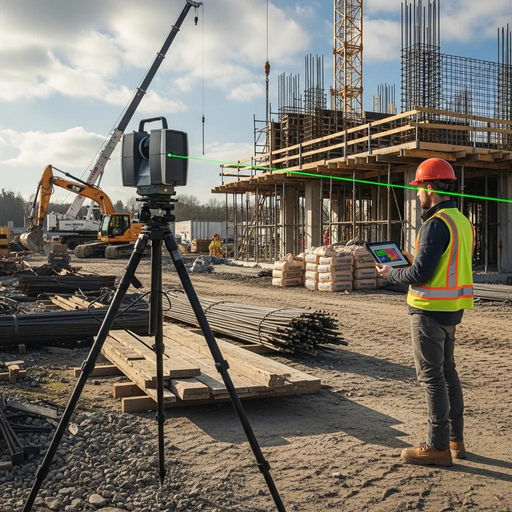
3D laser scanning produces dense point clouds that become reliable as-built baselines for renovations, retrofits, and verification of installed systems—an objective record that connects design to field conditions. Scans reduce uncertainty by documenting existing conditions in a format that overlays directly with BIM for clash detection and retrofit planning. For renovation work common in Atlanta’s urban core, scanning preserves dimensional accuracy and helps designers reconcile older structures with new systems. Those point clouds inform prefabrication tolerances, scope verification, and change management, making reality capture a key risk-reduction tool on complex jobs.
Key use cases for 3D scanning in construction:
- As-Built Documentation: A precise baseline for remodels and conversions.
- Renovation Planning: Early identification of structural or MEP interferences.
- Verification & QA/QC: Confirm installed elements meet model tolerances.
These use cases lead into practical scanning workflows and deliverables teams should expect when integrating point-cloud data with BIM.
Introductory table mapping scanning steps to BIM integration outcomes.
| Step | Process | Outcome |
|---|---|---|
| Capture Planning | Define control and scan targets | Efficient site coverage and registration accuracy |
| Registration & Cleanup | Align multiple scans and remove noise | Usable point cloud for model overlay |
| Modeling & Reconciliation | Overlay point cloud with BIM | Verified model updates and clash avoidance |
How Does 3D Scanning Support As-Built Documentation and Renovations?
A scanning survey starts with control setup and targeted captures to minimize occlusions and cover critical elements; captured data is then registered and processed into a consolidated point cloud. Deliverables usually include registered point clouds, orthographic exports, and extractable sections or elevations that designers and layout teams use to reconcile existing conditions with proposed work. For renovations, that baseline reduces surprises by revealing concealed structure, service runs, and geometric deviations that would otherwise cause schedule delays. The precise documentation supports more accurate prefabrication and fewer change orders during installation.
What Is the Process of Point Cloud Integration with BIM Models?
Point cloud integration follows a clear sequence: capture, registration, noise reduction, overlay with the BIM model, and reconciliation where model geometry is adjusted or annotated based on the scan. Common file formats (E57, LAS) and industry tools ease transfer between scanners and modeling environments; technicians run QA checks to ensure alignment within acceptable tolerances. Modelers extract planar surfaces, measured points, and pipe centerlines from the cloud to validate or update the BIM, creating a reconciled model suitable for clash detection and layout point export. That verification ensures layout instruments receive reliable coordinates, minimizing field adjustments and supporting steady installation workflows.
Why Should Atlanta Construction Firms Choose CCLS for Precision Layout Services?
Atlanta firms should choose Conway Coordination and Layout Services when they want a partner that combines Trimble Robotic Total Station workflows with VDC, BIM coordination, and 3D scanning to deliver verified layout and lower installation risk. Our regional experience across the Southeast—and our focus on precision and reliability—helps teams turn model intent into accurate field execution while protecting schedule and budget goals. We provide consultative engagements that align layout deliverables with prefabrication milestones so control points are ready when trade partners need them. Picking a provider with a coordinated technology stack and proven processes reduces layout-driven delays and creates clear QA/QC documentation for owners and contractors.
Below are brief, anonymized examples of outcomes we deliver in Atlanta-area projects:
- Commercial Fit-Out: Coordinated MEP layout reduced field rework and shortened installation by allowing prefabricated ceiling assemblies to install without adjustments.
- Renovation Baseline: 3D scanning informed model reconciliation that avoided unexpected demolition rework and kept the schedule intact.
- Structural Erection: Anchor bolt verification caught mislocated anchors before column erection, preventing a costly framing delay.
These outcomes show how technology and disciplined process translate into measurable savings and fewer schedule impacts. Next we explain how automated layout reduces rework and cost.
How Does Automated Layout Reduce Rework and Lower Project Costs?
Automated layout reduces rework by eliminating manual transcription errors between design intent and field marks: model coordinates export directly to layout instruments, removing layers where mistakes happen. That model-to-field pipeline supports prefabrication because components are built to the same coordinate set used onsite, which minimizes fit failures and saves installation labor. The cost benefit is twofold: direct savings from avoided rework and indirect savings from improved schedule reliability that lowers supervision and delay-related expenses. Early coordination and verification act as preventive controls that reduce downstream contingency spend and improve overall project economics.
What Case Studies Demonstrate CCLS’s Success in Atlanta Projects?
Our project examples consistently show measurable reductions in rework and time savings when model-driven layout and scanning are applied early in coordination. Typical anonymized outcomes include significant drops in field adjustments for MEP hangers, faster ceiling installs thanks to accurate hanger locations, and avoided change orders when anchor bolts were validated before steel delivery. These summaries illustrate how technology deployment—paired with disciplined processes—produces repeatable benefits across commercial, renovation, and structural work. For detailed portfolio examples, we invite teams to consult with us so we can match relevant metrics to your project type.
To take the next step, request a consultation with Conway Coordination and Layout Services to discuss your project’s tolerance requirements, prefabrication timeline, and model readiness—ask for Nathan Conway as the principal contact to review technology options and sequencing strategies. We’ll propose a tailored scope—combining Trimble Robotic Total Station layout, BIM/VDC coordination, and 3D scanning—to deliver verified layout outputs and verification reports that support installation and QA/QC. Engaging early in design or preconstruction maximizes automated layout benefits and embeds reliable control into your project’s critical path.
Frequently Asked Questions
What types of projects benefit most from automated construction layout services?
Automated construction layout is especially valuable on complex jobs: multi-story buildings, renovations, and MEP-heavy projects where tight tolerances and trade coordination matter. Robotic layout reduces errors and rework, which is critical in urban settings with limited space and tight schedules. Projects using prefabrication also benefit greatly—accurate control points help ensure off-site components fit together on arrival.
How does automated layout impact project timelines in construction?
Automated layout speeds schedules by cutting manual measurement and adjustment time. Robotic systems translate model coordinates into field marks quickly and reliably, removing repeated checks that slow progress. That efficiency improves trade coordination and prefabrication lead times, helping projects stick to planned schedules and avoid delay costs.
What training or expertise is required to operate robotic total stations effectively?
Effective operation requires specialized training in the equipment and the associated construction workflows. Operators need to know setup, model data import, and how to interpret measurements accurately. Familiarity with BIM and VDC is important because these systems feed the layout workflow. Companies commonly run formal training and ongoing education to keep teams current with best practices and new features.
Can automated layout services be integrated with existing construction workflows?
Yes—automated layout integrates with existing BIM and VDC workflows. The key is aligning team roles, training staff on new processes, and maintaining clear communication between design and field teams. When coordinated properly, robotic layout enhances accuracy and efficiency without requiring a wholesale change to established workflows.
What are the cost implications of implementing automated layout services?
While there’s an upfront investment in technology and training, automated layout often delivers long-term cost savings through reduced rework, better schedule adherence, and improved accuracy. Those savings typically outweigh initial costs—especially on projects that rely on prefabrication or have high rework risk. Better schedule performance also reduces indirect costs tied to delays.
How does 3D scanning complement automated layout services?
3D scanning provides verified as-built data that can be compared with design models, improving the reliability of layout inputs. Scanning reveals existing conditions in detail so layout is based on verified data, cutting surprises during installation. Together, scanning and automated layout raise overall project accuracy and reduce downstream changes.
Conclusion
Automated construction layout in Atlanta delivers clear advantages: higher precision, less rework, and more reliable timelines. By combining Robotic Total Stations with BIM coordination and 3D scanning, teams can convert design intent into accurate field execution and smoother installations. Working with a focused provider like Conway Coordination and Layout Services ensures your project benefits from experienced guidance and tailored solutions. Reach out to discuss how our services can improve your construction efficiency and reduce layout-driven risk.