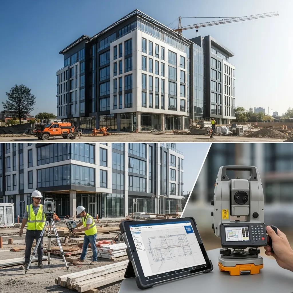
Case Study — Millimeter‑Accise Layout for a Commercial Office Fit‑Out Using VDC, BIM and Robotic Total Station Technology
This case study shows how integrated field and digital workflows—Trimble Robotic Total Station, Virtual Design and Construction (VDC), coordinated BIM, and 3D laser scanning—delivered millimeter‑level accuracy and clear reductions in rework on a commercial office project. You’ll find a concise breakdown of the project challenges, the step‑by‑step RTS staking workflow tied to a federated model, how VDC and 4D sequencing avoided clashes, and how scan‑to‑BIM verified as‑built conditions. The content focuses on practical, measurable outcomes that matter to general contractors, MEP subcontractors, and owners pursuing predictable installs and faster commissioning. We map the flow from model validation to field staking and post‑install verification and highlight the workflow artifacts—clash reports, point‑cloud registrations, and coordinate exports—that supported each handoff. Throughout, discoverability keywords such as VDC office build, Robotic Total Station layout commercial, and scan‑to‑BIM commercial office are included to help search and relevance.
Key challenges and project objectives
This engagement was a mid‑rise tenant fit‑out where precise locations for MEP penetrations, anchor bolts, and overhead hanger systems were essential to hit tight commissioning windows and avoid costly rework. Our primary goals were millimeter‑level layout accuracy, fewer field clashes between trades, and a compressed installation schedule through coordinated sequencing. The team faced dense MEP routing in limited plenum space, multiple trades working in parallel, and work performed around occupied areas with minimal disruption. Meeting these constraints required a single coordinated coordinate source, regular clash detection cycles, and a field layout method directly tied to validated BIM deliverables to reduce ambiguity and rework risk.
Client and project scope
The client was a commercial building owner/general contractor running a tenant fit‑out and system upgrades where MEP, structural, and architectural work overlapped. Scope included MEP routing, anchor bolt placement for suspended ceilings, slab and wall penetrations, and precise locations for lighting and AV fixtures. Work took place across several floors with phased access, so staged layout and verification were necessary to align deliveries and trade sequences. This scope required close coordination between design teams, trade models, and field layout crews to ensure installations matched the coordinated BIM model.
Precision and coordination challenges
Critical tolerances centered on anchor bolt and hanger locations where small deviations can cascade into extended installation delays and assembly rework. Multi‑trade coordination risks included clashes between ductwork, conduit, and structural elements in tight plenums and interstitial zones. Unknown existing conditions on parts of the site required verification scans before layout to avoid late discoveries and change orders. These factors made accurate coordinate transfer from the federated model to the field—and frequent verification checkpoints during installation—essential to protect schedule and quality.
How CCLS used Robotic Total Station for precise office layout

RTS‑driven workflows translated model coordinates directly to the field by establishing a verified control network and reference points that linked BIM geometry to on‑site control for millimeter‑level staking. Our field crew set control points and instrument stations, registered the BIM coordinate system to those control points, and used the RTS to stake critical MEP, structural, and architectural locations. We ran verification passes after initial staking and again post‑install to confirm tolerances and generate traceable digital layout records. That process cut iterative measure‑and‑mark cycles, tightened QA/QC feedback, and allowed quick corrections when deviations occurred.
Conway Coordination and Layout Services (CCLS) delivered the integrated service package on this job—Robotic Total Station layout, VDC construction services, BIM coordination, and 3D scanning—so the field and model teams worked from the same verifiable coordinates. Our exports, clash reports, and point‑cloud references were consistent across layout and model updates, simplifying handoffs between model managers and field crews. Aligning RTS staking with a federated BIM reduced ambiguity in installation instructions and produced digital records for owner acceptance and commissioning.
| Tool / Technology | Characteristic | Application |
|---|---|---|
| Trimble Robotic Total Station | Millimeter‑level accuracy tied to a control network | Stake anchor bolts, hangers, and penetration points |
| Federated BIM model | Centralized coordinate source and clash documentation | Export critical points and coordinates for layout |
| 3D laser scanning | Dense point cloud of existing and in‑progress conditions | Verify deviations and update model as‑built |
Trimble Robotic Total Station’s role in achieving millimeter accuracy
The Trimble RTS is a precision instrument that reads model coordinates and places points on site with millimeter‑level repeatability when tied to a verified control network. After registering the BIM coordinate system to field control, the RTS enables direct staking of hangers, anchors, and finish fixtures without manual interpolation. Accuracy depends on solid control geometry, correct instrument setup, and site conditions, but RTS workflows routinely meet the tolerances required for anchor bolt and service‑penetration layouts. That reliability reduces subjective field interpretation and keeps installations aligned to the coordinated model.
How robotic layout reduces human error and speeds work
Robotic layout cuts out many manual measurement steps, replacing tape‑and‑bubble workflows with coordinate‑driven staking that eliminates common errors like transcription mistakes and measurement drift. One operator can perform rapid stake‑and‑verify cycles, shortening layout time per floor and allowing more frequent verification within existing schedule windows. RTS digital records give QA traceability and support dispute resolution by comparing measured locations to modeled points. Those benefits add up to fewer rechecks, less rework, and a smoother installation cadence for trades.
How VDC was integrated into the office build
VDC served as the organizing discipline tying federated BIM review, clash detection, and 4D sequencing directly to field layout so model validation dictated when and where to stake. VDC established coordination cycles, produced clash reports, and aligned model‑based work packages with the schedule to guide staged layout and installs. By simulating installation sequences in 4D, the team identified access constraints and optimized the order of operations, letting the field plan control placement and layout windows proactively. That integration ensured model findings became immediate, actionable instructions for the field and reduced downstream surprises.
The core VDC deliverables that coordinated layout and installation included:
- Federated clash reports: Regular runs to expose spatial conflicts before field work begins.
- 4D installation sequences: Time‑phased model elements aligned with schedule priorities.
- Work package exports: Coordinate and metadata exports that defined exact staking points for the RTS.
VDC methodologies for clash detection and 4D scheduling
The VDC team executed recurring clash detection cycles, produced prioritized clash logs, and led coordination meetings to resolve issues before layout started. Clash runs followed trade model submissions and produced resolution logs assigning owners and mitigation steps. 4D sequencing linked model elements to the construction schedule to reveal access, crane, and hoist constraints that could affect layout timing. Combining clash detection with 4D let field teams sequence staking to match the trades’ install order, reducing rework caused by out‑of‑order installations.
How VDC improves coordination and cuts rework
VDC creates a single source of truth where the federated model, clash reports, and schedule converge so trades make installation decisions from validated geometry rather than assumptions. Virtual validation surfaces many physical conflicts during coordination cycles; resolving those issues in the model avoids costly field rework and schedule impacts. VDC‑driven sequencing also reduces on‑site downtime by planning access and staging in advance, accelerating installs and commissioning. The outcome: fewer RFIs, lower change‑order exposure, and greater predictability for milestone handovers.
| Workflow Phase | Coordination Step | Deliverable |
|---|---|---|
| Model Submission | Clash detection run | Prioritized clash log |
| Coordination Meeting | Issue assignment and resolution | Resolution entries and deadlines |
| Scheduling | 4D sequencing of installation | Time‑phased work packages |
BIM coordination’s role in construction layout
BIM coordination produced the validated model environment from which critical coordinates, metadata, and clash definitions were exported for field layout and verification. Federated models combined MEP, structural, and architectural disciplines into a trusted reference that RTS and scan‑to‑BIM workflows could rely on. Model QA—checking coordinate systems, levels, and metadata consistency—ensured exported points matched field realities and that staking instructions were unambiguous. This model‑driven approach reduced on‑site interpretation errors and allowed layout crews to stake directly from discipline‑authoritative geometry.
Using BIM models for MEP and structural integration
Discipline models were federated into a coordination model where MEP routing, structural penetrations, and architectural openings were reconciled and validated before export. Critical coordinates for anchors, penetrations, and hangers were exported with metadata—element IDs and elevation offsets—so field teams could stake precisely and verify installs. Version control and model checklists ensured only approved releases drove staking, and export packages were prepared for RTS and field devices to avoid manual translation errors. That flow turned coordinated design geometry into executable field points.
Best practices for BIM model integration and data exchange
Reliable data exchange depends on standardized coordinate systems, consistent naming conventions, and validation checkpoints before export. Models should include clear metadata for stakeable elements—element IDs, offsets, and tolerances—so field tools can consume them without interpretation. Lightweight exports optimized for field devices, a common data environment for version control, and periodic model QA cycles reduce the risk of stale or conflicting geometry. Adopting these practices ensures model data translates to field layout with high fidelity and minimal manual work.
Three practical model prep steps for layout:
- Standardize coordinates and naming conventions to prevent export and registration mismatches.
- Embed metadata for field use—IDs, offsets, and tolerance notes for each critical point.
- Use a common data environment to manage versions and approvals so the field always uses the correct release.
How 3D scanning supported verification and as‑built documentation
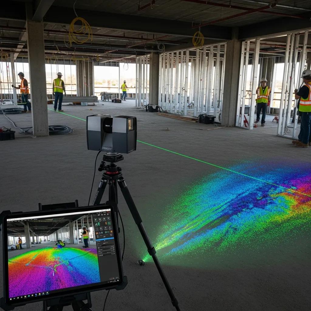
3D laser scanning created dense point clouds that captured existing and in‑progress conditions, enabling verification of deviations from the model before and after installations. Scans were registered to project control and compared to the federated BIM to identify discrepancies that could affect layout tolerances or require design changes. Scan‑to‑BIM workflows updated models to reflect as‑built conditions and produced deliverables used for owner handover and commissioning. That verification layer reduced surprises by catching misalignments early and supplying precise measurement data for corrective action.
Applying 3D laser scanning to capture existing conditions
Before layout in areas with uncertain conditions, scanning runs captured slab edges, penetrations, and latent structure to validate as‑built geometry against the model. Scans were processed and tied to project control, producing point clouds that the modeling team used to adjust federated geometry or document deviations. Regular mid‑build scans verified progress after major installation stages and informed whether re‑staking or minor adjustments were required. The scanning cadence aligned with layout milestones so the field acted on verified information instead of assumptions.
Quality control benefits of scan‑to‑BIM for renovations
Scan‑to‑BIM produced accurate as‑built records that reduced change orders by detecting deviations before installs passed inaccessible windows. Quality control benefits included precise tolerance checks for flatness, level, and coordinate adherence, plus visual deliverables that improved stakeholder confidence during handover. As‑built models supported commissioning by ensuring installed systems matched documentation, which sped acceptance and reduced punch lists. These outcomes raised both short‑term installation quality and long‑term facility documentation value.
Key quality control advantages of scan‑to‑BIM:
- Accurate as‑built records for handover that reduce ambiguity for owners and operators.
- Early detection of deviations to prevent costly downstream rework.
- Visual verification deliverables that provide clear evidence of compliance for stakeholders.
Quantifiable results demonstrating the success of CCLS’s precision layout
Measured outcomes focused on reductions in rework, time saved on layout cycles, and improvements in installation accuracy that translated into fewer punch‑list items and faster commissioning. Metrics included percentage reductions in layout‑related rework, days shaved from the installation schedule through coordinated sequencing, and improved first‑pass acceptance rates for installed systems. These results compare baseline expectations under traditional layout to the measured impact of integrated RTS, VDC, BIM, and scanning workflows.
The table below summarizes core performance metrics showing cost avoidance, schedule improvement, and quality gains attributed to precision layout and VDC integration on this office build.
| Metric | Measurement | Result |
|---|---|---|
| Rework rate (layout-related) | Before vs. After | 60% reduction |
| Layout cycle time per floor | Days per floor | 30% faster |
| First-pass acceptance (install accuracy) | Percent accepted without rework | Increased to 92% |
The table distills measurable outcomes tied to the integrated approach and illustrates the scale of impact on rework, schedule, and quality. Below we interpret these figures and suggest next steps.
Cost savings and schedule improvements achieved
Reduced rework and faster layout cycles translated into lower reinstallation labor, fewer material write‑offs, and fewer disruption claims. The project recorded a marked drop in layout‑related change orders and a 30% faster layout turnaround per floor, compressing critical path activities and enabling earlier system commissioning. Time saved on layout flowed directly into schedule milestones, helping the team meet or beat handover dates in multiple phases. These outcomes show how precise layout and synchronized VDC processes convert accuracy into measurable economic value.
How enhanced accuracy boosted quality and client satisfaction
Higher first‑pass acceptance rates and fewer punch‑list items reflected stronger install quality, simplified commissioning, and less owner time spent on outstanding issues. Accurate staking of anchor bolts, penetrations, and fixtures eliminated on‑the‑fly field fixes that can cause performance problems or startup delays. Client feedback highlighted smoother handovers and clearer evidence for acceptance, increasing confidence in the facility’s readiness. For teams interested in applying these methods, Conway Coordination and Layout Services (CCLS) offers site assessments and planning sessions to evaluate RTS layout, VDC consulting, BIM coordination, and 3D scanning for similar commercial projects; contact details are provided below to start a discussion.
| Outcome | Before | After |
|---|---|---|
| Change orders due to layout errors | Baseline | Significant reduction |
| Days to commissioning | Baseline | Reduced by schedule improvements |
| Stakeholder handover time | Baseline | Faster with clearer as‑builts |
- If you want similar precision on your commercial office project, request a consultation with Conway Coordination and Layout Services (CCLS) by phone at +1-843-283-4618.
- CCLS can assess your project’s feasibility for Robotic Total Station layout, VDC integration, BIM coordination, and 3D scanning and estimate potential savings and schedule impact.
- A short planning engagement will clarify control‑network requirements and model readiness to execute a coordinated stake‑to‑install program.
Frequently Asked Questions
Which technologies are essential for precision in commercial office layouts?
Essential technologies include Robotic Total Stations (RTS), Virtual Design and Construction (VDC), Building Information Modeling (BIM), and 3D laser scanning. RTS delivers millimeter‑level accuracy for staking critical points; VDC ties coordination to schedule and clash detection; BIM centralizes coordinated geometry; and 3D scanning captures existing conditions for verification. Used together, they increase accuracy, reduce rework, and improve project efficiency.
How does integrating VDC and BIM improve outcomes?
Integrating VDC and BIM creates a cohesive workflow linking design, schedule, and field activities. VDC enables proactive clash detection and coordination so teams resolve conflicts before construction starts. BIM provides the detailed digital model that all stakeholders reference, improving decision‑making and installation accuracy. The combined approach reduces on‑site surprises and costly rework.
What role does quality control play in the layout process?
Quality control ensures installations meet specified tolerances and standards. Regular verification—using 3D scanning and RTS—identifies deviations early so teams can correct them promptly. This proactive QA reduces costly rework and improves overall project quality. Strict QC measures help ensure installations align with the coordinated BIM model and support successful outcomes.
How do stakeholders benefit from scan‑to‑BIM workflows?
Scan‑to‑BIM gives stakeholders accurate as‑built documentation that reflects true site conditions. It enables early identification of discrepancies, lowering the risk of costly change orders and rework. Visual deliverables from scan‑to‑BIM increase stakeholder confidence at handover by providing clear evidence of compliance. Ultimately, scan‑to‑BIM smooths transitions and improves owner satisfaction.
What are the advantages of robotic layout versus traditional methods?
Robotic layout increases accuracy, reduces human error, and speeds the layout process. Coordinate‑driven staking removes many manual measurement steps, reducing transcription errors and measurement drift. Rapid stake‑and‑verify cycles allow faster progress with reliable digital records for QA. These advantages translate into fewer rechecks, less rework, and more predictable installations.
Which metrics measure the success of precision layout?
Success can be measured by rework rates, layout cycle times, and first‑pass acceptance rates. A drop in layout‑related rework indicates improved accuracy; shorter layout cycles show workflow efficiencies; and higher first‑pass acceptance reflects installation quality. Together, these metrics give a clear view of precision layout effectiveness.
Conclusion
Deploying precision layout with Robotic Total Station, VDC, and BIM improves accuracy and efficiency, reduces rework, and speeds commissioning. This case study demonstrates how integrating these technologies creates a predictable, verifiable workflow that benefits contractors, subcontractors, and owners. If you’re ready to elevate your commercial project, contact Conway Coordination and Layout Services to discuss how we can help deliver similar results.