Practical Guide to Fabrication‑Ready BIM: Streamlined BIM Coordination and VDC Integration
Fabrication‑ready BIM models are digital, shop‑grade representations of building systems that include precise geometry, fabrication metadata, and clear assembly intent—everything needed to drive shop drawings and offsite manufacturing. By combining LOD 400 geometry, coordinated clash results, and automated shop‑drawing outputs, these models give fabricators and installers unambiguous instructions that reduce rework and compress schedules. This guide walks through how fabrication‑ready BIM, disciplined BIM coordination, and Virtual Design & Construction (VDC) practices work together to deliver measurable efficiencies: fewer RFIs, faster installs, and smarter material use. You’ll find clear LOD expectations, coordination workflows from clash detection through spooling, VDC use cases for sequencing and 4D/5D planning, and the practical technologies that enable precise layout and digital‑twin handoffs. We also explain how Conway Coordination and Layout Services (CCLS) supports fabrication‑ready workflows with specialized modeling, precision layout tools, and VDC consulting—always focused on best practices and measurable ROI. Keywords like fabrication‑ready BIM models, LOD 400 BIM, shop drawing generation, and BIM coordination appear throughout to connect concepts with implementation steps.
What fabrication‑ready BIM models are and how they drive construction efficiency
A fabrication‑ready BIM model is a federated dataset built to the accuracy and detail required for manufacturing and assembly—typically LOD 400. The efficiency comes from precise geometry paired with fabrication metadata—part numbers, material specs, connection details, and tolerances—so models can be turned into shop packages and CNC inputs without guesswork. The main benefit is less ambiguity for fabricators and installers, which cuts onsite rework, speeds procurement, and shortens lead times for prefabricated assemblies. Knowing exactly what deliverables a fabrication‑ready model must include clarifies handoffs and smooths coordination with manufacturers and suppliers.
The table below maps common model elements to their LOD attributes and the deliverables expected by manufacturing or installation teams. This explicit mapping helps teams confirm LOD 400 requirements before production begins.
| Element | LOD Attribute | Deliverable |
|---|---|---|
| MEP Duct Runs | Accurate as‑built geometry and connection spools | Spool drawings, cut lists, bending schedules |
| Structural Steel Members | Fabrication geometry, connection plates, bolt patterns | Shop drawings, connection detail sheets, BOM |
| Connection Details | Tolerances, welding/bolting information, part numbers | Connection detail sheets with material callouts |
| Equipment Mounts | Anchor layouts and embed coordinates | Mounting plates and anchor bolt schedules |
That mapping removes interpretation risk for fabricators and installers. When those items exist in the model, RFIs drop and downstream automation for shop drawings and CNC tooling becomes direct. Clear deliverables also improve procurement planning and tighten the connection between design, fabrication, and field installation.
What makes a model LOD 400 and fabrication‑ready?
LOD 400 models contain fabrication‑specific geometry and the metadata needed for manufacturing—objects represent actual fabricated components rather than conceptual placeholders. That means precise dimensions, splice and connection details, material and finish specs, and part numbers that tie to procurement and shop processes. Fabricators use that information to create spools, bending schedules, and CNC files; without accurate metadata, those outputs require manual work that introduces error and delay. In practice, modelers rely on parametric families with embedded fabrication parameters and standardized naming so automated extraction tools can produce consistent shop sheets.
Those attributes feed automated shop‑drawing generation and clash‑detection workflows, preserving prefabrication integrity. Well‑implemented LOD 400 practice makes each model element a single source of truth for both shop and field crews.
How fabrication‑ready models improve prefabrication and reduce mistakes
Fabrication‑ready models enable clash‑free, dimensionally accurate shop drawings and provide BOMs and spooling instructions that drive fabrication machinery. When geometry and metadata are complete, software pipelines can export schedules, spool maps, and CNC‑compatible files without manual redrafting. That reduces common errors—mis‑measured parts, mismatched connections, incomplete material lists—that often trigger RFIs and rework on site. Validating fit and clearances in the model prevents costly shop rework and late design changes, streamlining logistics and shortening project timelines.
Better prefabrication workflows also raise factory QA and smooth site assembly, making modular and offsite manufacturing more predictable and cost‑effective. The result is less waste, fewer delays, and faster commissioning when fabrication matches the model intent.
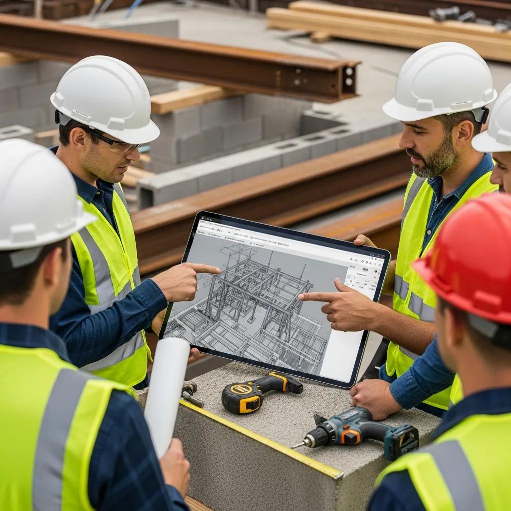
How BIM coordination services streamline fabrication workflows

BIM coordination is the repeatable process of federating discipline models, running clash detection, resolving conflicts, and validating model data so handoffs to fabrication are dependable and repeatable. The work involves scheduled federations, prioritized clash reports, coordination meetings, and defined mitigation paths that turn coordination outputs into model updates and RFIs when needed. The core advantage is catching and fixing conflicts early—before fabrication or installation—so change orders and shop rework decline. A consistent coordination cadence creates accountability across trades, improves version control, and keeps the model as the single source of truth for shop drawing generation.
Below we map common coordination activities to measurable benefits so teams can prioritize coordination work in preconstruction and design phases.
| Model Element | Coordination Task | Benefit/Metric |
|---|---|---|
| Federated Model | Regular clash detection runs | Fewer onsite clashes and lower rework rates |
| MEP Systems | Clearance verification and routing coordination | Less conduit rerouting during install |
| Structural Interfaces | Connection checks and tolerance reviews | Reduced shop rework on connections |
| Model Handoffs | Export of fabrication metadata | Faster shop drawing automation and QC |
These examples show how focused coordination tasks produce quantifiable benefits and let teams measure improvements across fabrication and installation. When model validation includes export‑ready metadata, the handoff to automated shop drawing generation is smoother and more predictable.
The coordination workflow typically follows a repeatable loop—clash detection, model update, fabrication handoff—and that repeatability is what scales improvements across projects. A structured coordination process preserves the fidelity of fabrication‑ready models and supports continuous improvement in prefabrication pipelines.
What BIM coordination does for clash detection and risk mitigation
BIM coordination consolidates discipline models, identifies interferences, and assigns resolution actions that prevent downstream conflicts during fabrication and installation. Clash detection classifies issues—hard clashes, soft clashes, clearance problems—and ranks their severity so teams can triage fixes cost‑effectively. Resolving clashes during design or pre‑fabrication reduces the chance fabricators will build parts that don’t fit, a leading cause of onsite rework and schedule delays. Coordination delivers clash reports, resolution logs, and tracked model revisions that create accountability and enable post‑project audits.
Early clash resolution tightens fabrication tolerances and builds trust between designers and fabricators, supporting more ambitious prefabrication strategies and better lead‑time predictability. Efficient clash workflows therefore have a direct, positive impact on fabrication efficiency and installation speed.
How automated shop‑drawing generation speeds production and improves accuracy
Automated shop‑drawing generation converts accurate model geometry and metadata into standardized shop sheets, spools, BOMs, and CNC files using extraction scripts and templates. This removes manual drafting steps by using parametric families and metadata tags that feed preconfigured templates for dimensioning, labels, and cut lists. The outcome is much faster turnaround from model update to fabrication‑ready documents, fewer transcription errors, and consistent documentation across trades. Automation also ensures model changes propagate quickly into shop drawings, shrinking the lag between design updates and manufacturing output.
By automating repeatable drafting tasks, teams can focus on verification and quality control, raising precision and shortening the path from design to production—especially valuable when schedules change frequently or spool volumes are large.
The role of VDC in optimizing fabrication and installation workflows
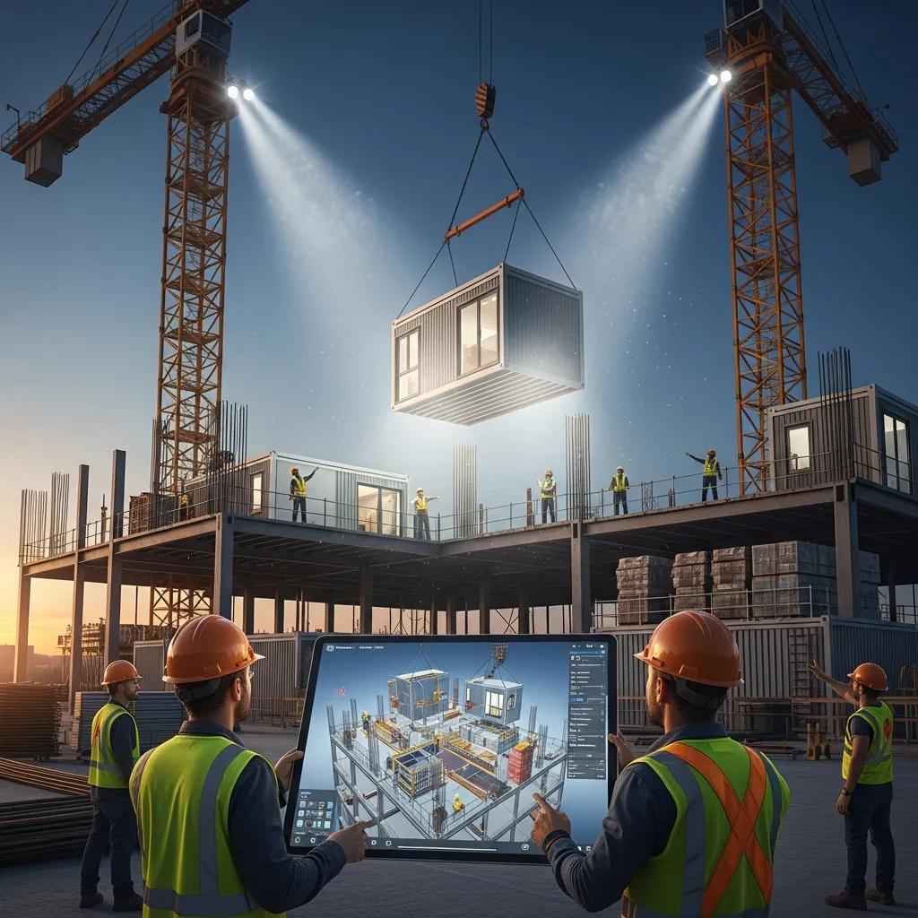
Virtual Design & Construction (VDC) applies model‑based workflows to planning, sequencing, and performance optimization so fabrication and installation align with schedule and cost objectives. VDC brings together 4D sequencing, 5D cost modeling, and constructability reviews to simulate how prefabricated assemblies will be produced, transported, and installed. That simulation improves decisions by exposing interdependencies and schedule‑sensitive fabrication constraints before any material is produced. Key benefits include optimized fabrication sequencing, reduced site disruption, and improved cash flow via predictable procurement and just‑in‑time delivery.
VDC functions as a process‑level extension of BIM: it moves beyond geometry to include logistics, schedule, and cost so prefabrication delivers real value. By simulating fabrication‑to‑installation pathways, VDC minimizes surprises and creates a framework for continuously improving offsite manufacturing strategies.
- VDC reduces onsite schedule conflicts through 4D sequencing that aligns fabrication deliveries with installation windows.
- VDC improves procurement timing by integrating 5D cost data and lead‑time constraints into model‑based planning.
- VDC supports constructability checks that identify prefabrication risks and recommend mitigations before shop production.
Combined, these benefits raise predictability across fabrication and installation, allowing stakeholders to optimize resources and cut downstream costs. Using VDC as an operational tool creates a continuous feedback loop between the shop floor, logistics planners, and installation crews—strengthening the value of fabrication‑ready BIM.
How VDC and fabrication‑ready BIM work together
VDC uses model geometry and metadata from fabrication‑ready BIM to run sequencing simulations, test assembly logistics, and confirm manufacturing readiness before shop production. 4D animations let teams evaluate installation windows, crane lifts, and site access constraints that affect module sizing and prefabrication sequencing. Simulating transport and install uncovers constructability issues that can be fixed in the model—preventing costly fabrication rework or modules that are too large to handle on site. VDC serves as a pre‑manufacture assurance layer that verifies models are not just accurate but assembly‑ready in real conditions.
This integration makes fabrication decisions responsive to site realities and schedule constraints, helping teams balance factory efficiency with installation practicality. The result is prefabrication that’s efficient to produce and straightforward to install.
What VDC consulting delivers for fabrication projects
VDC consulting provides implementation plans, sequencing strategies, and performance metrics that help teams adopt fabrication‑friendly workflows. Typical consulting work includes process design for model validation, coordination protocols, and a roadmap for bringing 4D/5D simulations into procurement and fabrication planning. The outcome: fewer RFIs, better logistics coordination, and lower onsite labor costs thanks to higher prefabrication levels and clearer installation sequencing. Consultants also establish measurable metrics—reductions in change orders and days saved—that owners and contractors can use to evaluate VDC’s impact.
By converting VDC principles into practical workflows, consulting accelerates adoption and helps organizations quantify returns on prefabrication investments—especially useful for teams moving toward modular construction or scaling prefabrication across projects.
How fabrication‑ready BIM is tailored for different industries
Fabrication‑ready BIM adapts to industry needs by customizing families, metadata, and validation rules to sector standards—MEP spooling, sterile environments in healthcare, or heavy modular units in industrial facilities. The mechanism is sector‑focused configuration: model libraries, tolerance templates, and coordination checklists are adjusted so outputs meet regulatory and functional requirements. For example, healthcare projects emphasize validated penetrations and commissioning packages, while industrial projects focus on heavy‑lift coordination and structural connections. Tailored model outputs make fabrication packages compliant, installable, and optimized for each project’s operational constraints.
- MEP prefabrication emphasizes spooling, bend and cut lists, and service coordination—requiring parametric families and continuity checks to generate shop outputs.
- Structural prefabrication prioritizes connection details, weld schedules, and plate geometry—requiring explicit bolt patterns and erection sequencing in the model.
- Sector adaptations often include extra metadata for regulatory compliance, testing requirements, and commissioning data for operations handoff.
These customizations ensure fabrication‑ready BIM addresses each industry’s specific demands while preserving the efficiency advantages of prefabrication and offsite manufacturing.
How BIM supports MEP and structural prefabrication
BIM enables MEP prefabrication through automated spooling, bend tables, and coordinated routing that reduce field clashes and shorten installation hours. For structural prefabrication, BIM produces precise member geometry, connection plates, and bolt schedules that feed shop drawings and erection plans. Common data exports—IFC files and discipline‑specific schedules—let fabrication software and CNC tools consume model data directly, reducing manual interpretation. Consistent naming conventions and embedded fabrication parameters make automated extraction of fabricator‑ready information possible and allow quality checks before production.
When MEP and structural teams follow consistent modeling standards, handoffs to shops become efficient, production accelerates, and fit‑up in the field improves. Interoperability and disciplined model management are essential to that success.
Advantages of fabrication‑ready BIM in healthcare and industrial projects
In healthcare, fabrication‑ready BIM reduces onsite disruption and streamlines commissioning by delivering prefabricated modules and assemblies that minimize work in sensitive areas. The approach includes validated penetrations, clean‑room‑compatible components, and documentation packages that support inspections and commissioning. In industrial projects, fabrication‑ready models enable heavy prefabrication of process skids and modular units with exacting connection details and lifting points—improving safety and reducing onsite assembly time. Both sectors see improved QA, predictable installation sequencing, and faster turnover to operations.
Those sector‑specific advantages lower operational risk and speed time‑to‑value for owners, reinforcing the case for investment in fabrication‑ready modeling practices.
Which technologies and expertise does CCLS use to deliver fabrication‑ready BIM?
Conway Coordination and Layout Services (CCLS) combines precision layout tools, 3D scanning, and disciplined BIM modeling to produce fabrication‑ready deliverables. Our approach pairs federated model validation and clash resolution with field‑verified layout using Trimble Robotic Total Station workflows to translate model coordinates into accurate site locations. We emphasize robust model validation, parametric family standards, and automated shop‑drawing pipelines so clients receive reliable spooling, BOMs, and fabrication data. As a family‑owned firm focused on BIM Modeling and Coordination, VDC Construction Services, and VDC Consulting, CCLS wraps these technologies in a consulting framework aimed at eliminating rework and improving constructability planning.
If your team wants to explore fabrication‑ready modeling or request a consultation, contact Nathan Conway at Conway Coordination and Layout Services. Nathan can discuss project‑specific modeling standards, layout capabilities, and ROI assessments. CCLS’s hands‑on experience delivering precise modeling and layout helps clients achieve seamless coordination between design, shop fabrication, and field installation.
The sections that follow summarize core technologies and show how they map to fabrication outcomes so teams can prioritize the right tools.
Key tools and capabilities in a fabrication‑ready workflow—and why they matter:
- Trimble Robotic Total Station for translating model coordinates to field layout and guaranteeing installation accuracy.
- 3D laser scanning and point‑cloud processing for validating as‑built conditions and supporting prefabrication fit checks.
- Mainstream BIM authoring and federation tools to generate LOD 400 geometry and metadata for shop‑drawing automation.
These technologies pair digital precision with field verification to reduce discrepancies between model and site. Prioritizing them reduces rework and creates a reliable path from model to fabrication to installation.
How Trimble Robotic Total Station improves precision layout
Trimble Robotic Total Station workflows map BIM coordinates to the built environment with repeatable accuracy. We export model coordinates to field devices that guide the instrument to mark anchor points, embed positions, and layout lines—supporting tight fabrication tolerances. That accuracy lowers installation errors from rough layout and ensures prefabricated components fit as designed, limiting onsite modifications. Bringing robotic total station workflows into BIM coordination closes the loop between digital design and physical installation and supports QA documentation for as‑built records.
Model‑driven layout also improves verification: teams can re‑scan installed assemblies and compare point clouds to the model to quickly find and correct deviations. These capabilities reinforce the value of aligning model accuracy with field execution.
How 3D scanning and digital twins support fabrication and facility management
3D scanning captures precise as‑built geometry in point clouds that register to BIM for verification, clash remediation, and prefabrication fit checks before shop production. When scanned data is reconciled with the model, teams can catch deviations and update fabrication inputs—preventing manufacture of parts that won’t fit existing conditions. Digital twins extend this by preserving as‑built geometry, system metadata, and maintenance attributes for long‑term facility management and future retrofits. The scan→model→shop→scan feedback loop keeps facility data accurate and actionable.
Together, scanning and digital‑twin practices bridge construction and operations, making fabrication‑ready BIM a long‑term asset for owners and maintenance teams—not just a one‑time construction deliverable.
Measurable benefits and ROI from fabrication‑ready BIM
Fabrication‑ready BIM delivers measurable ROI through reduced rework, optimized material ordering, faster installation rates, and lower onsite labor hours. The logic is simple: precise models plus effective coordination means fabricators build correct components, deliveries hit installation windows, and sites need fewer corrective actions. Project teams can track metrics—RFIs, change orders, days saved, and material waste—to quantify improvements. A project‑level ROI assessment starts with baseline measurements and compares outcomes after adopting fabrication‑ready practices to demonstrate savings.
The table below links common cost and time attributes to typical impacts seen when fabrication‑ready BIM is applied—helpful for prioritizing interventions.
| Metric | Attribute | Typical Impact |
|---|---|---|
| Rework Hours | Onsite corrective labor | Reduced by eliminating design‑related shop errors |
| Material Waste | Offcuts and over‑ordering | Lowered through accurate takeoffs and BOMs |
| Schedule Days | Install duration | Shortened through prefabrication and sequencing |
| RFIs/Change Orders | Design clarity | Fewer inquiries and revisions when models are complete |
This view helps teams focus on metrics that drive financial and schedule performance. Measuring these attributes supports data‑driven decisions about further investment in VDC and fabrication workflows.
Primary ROI vectors and how they translate into project value:
- Rework reduction: fewer onsite corrections save labor and compress schedules.
- Material optimization: precise takeoffs reduce procurement costs and waste.
- Faster installs: prefabrication and sequencing shorten critical‑path durations.
Tracking these vectors provides a practical way to quantify returns from fabrication‑ready modeling. Establishing baselines lets teams demonstrate year‑over‑year gains as fabrication practices mature.
How BIM reduces costs and material waste
BIM lowers costs and waste by producing accurate material takeoffs, avoiding duplicate purchases, and enabling offsite fabrication that optimizes cutting patterns and inventory. Model‑driven quantity extraction and validated spooling produce tightly scoped BOMs for fabricators, reducing ordering errors and excess stock. Prefabricated assemblies made under factory QA with optimized nesting also cut onsite waste. By reducing change orders and on‑site corrections, BIM directly decreases labor and material costs associated with rework.
Problem → intervention → impact:
- Problem: Mis‑measured components → Intervention: Accurate model geometry → Impact: Fewer shop remakes.
- Problem: Excess material orders → Intervention: Precise takeoffs → Impact: Reduced waste and lower procurement costs.
- Problem: Late design changes → Intervention: Automated shop‑drawing regeneration → Impact: Faster response with fewer errors.
Case studies that show fabrication‑ready BIM success
Project vignettes consistently show outcomes like shorter schedules and fewer change orders. Typical case studies follow a pattern: challenge (complex interfaces or poor coordination), solution (LOD 400 modeling, spooling, VDC sequencing), and outcome (reduced RFIs, faster installs, clearer handoffs). Exact numbers come from project portfolios, but the trend is clear—prioritizing model fidelity and coordination makes fabrication and installation more predictable and cost‑effective. Requesting project‑specific case studies or ROI assessments lets stakeholders see comparable results for their own work.
For teams ready to quantify potential savings, Conway Coordination and Layout Services offers consultations to review project scope, set measurement metrics, and produce tailored ROI assessments led by Nathan Conway. That consultative approach turns modeling improvements into financial projections and implementation roadmaps that support informed decisions.
Frequently Asked Questions
What’s the difference between LOD 400 and lower BIM levels?
LOD 400 is a fabrication‑grade level of detail that includes precise geometry and full metadata for manufacturing. Lower levels—LOD 200 or LOD 300—are less specific: LOD 200 is often conceptual sizing and shape, and LOD 300 adds more geometry but usually lacks the fabrication specifics needed for direct shop drawing generation. Knowing these differences ensures models meet the needs of each project phase.
How can teams collaborate effectively during BIM coordination?
Effective BIM coordination relies on regular communication, scheduled coordination meetings, and shared digital platforms. Clear roles and responsibilities, consistent clash‑detection workflows, and a centralized federated model keep everyone working from the same data. Documenting decisions and maintaining a shared resolution log improve accountability and smooth handoffs between design and fabrication teams.
What role does QA play in fabrication‑ready BIM?
Quality assurance is essential: it confirms models meet the standards required for production. QA steps validate model accuracy, check compliance with specifications, and ensure all required metadata is present. Implementing QA at multiple stages catches errors early and reduces costly rework during fabrication and installation, improving overall project reliability.
How does integrating VDC and BIM improve project results?
Integrating VDC with BIM aligns design, schedule, and cost so teams can simulate and optimize construction before work begins. VDC uses BIM data for 4D and 5D modeling to reveal potential issues early, improving decision‑making and reducing delays. This approach streamlines procurement, resource planning, and ensures fabrication aligns with installation sequencing—leading to more predictable delivery.
What common challenges arise when implementing fabrication‑ready BIM?
Common challenges include change resistance from traditional workflows, the need for trained staff, and integrating multiple software platforms. Ensuring data interoperability and maintaining consistent model accuracy across disciplines are also frequent issues, especially on complex projects. Overcoming these challenges requires training, clear communication, and standardized processes to support collaboration and data sharing.
How do teams measure the success of fabrication‑ready BIM?
Measure success with KPIs like reductions in rework hours, material waste, RFIs, and change orders. Compare baseline metrics to post‑implementation results to quantify improvements. Tracking installation speed and shop‑drawing accuracy also helps demonstrate BIM’s value. Regular metric reviews allow teams to refine processes and show stakeholders the return on BIM investments.
Conclusion
Fabrication‑ready BIM models drive real improvements on projects: less rework, smarter material use, and faster installations. The approach tightens coordination across design, fabrication, and field teams so stakeholders see fewer surprises and better outcomes. To explore how these practices can benefit your next project, reach out for a consultation with our team. Discover how fabrication‑ready BIM can improve predictability, reduce cost, and accelerate delivery.