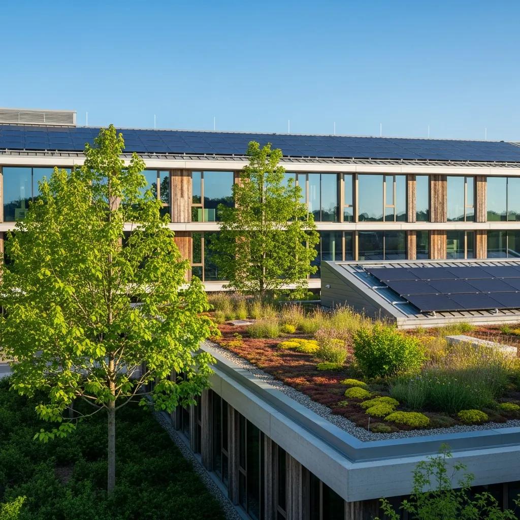
Integrating Renewable Energy into Sustainable Buildings: Precision Coordination and Digital Construction
Delivering reliable renewable energy on buildings depends on tight alignment between design intent, structural limits, and field execution. When those elements drift apart, energy performance, timelines, and budgets all pay the price. This article shows how precision coordination and digital construction tools—Virtual Design and Construction (VDC), Building Information Modeling (BIM), 3D scanning, and robotic layout—work together to cut rework and produce predictable results for solar, geothermal, and small wind systems. You’ll get practical workflows for VDC on commercial solar, BIM-driven clash detection for renewable systems, measurable benefits from robotic total station layout, and how point-cloud scans reduce retrofit risk. We also map these methods to concrete uses like building‑integrated photovoltaics (BIPV) and geothermal loop field layout, with an emphasis on energy performance and lifecycle handoff. Conway Coordination and Layout Services (CCLS), led by Nathan Conway, provides VDC, BIM coordination, 3D scanning, point cloud rendering, and Trimble robotic total station layout to support these workflows and offer project-specific coordination and field verification. The article is structured into clear sections covering VDC benefits, BIM capabilities, precision layout technologies, common challenges and mitigations, measurable efficiencies, and practical service applications.
How Does Virtual Design and Construction Enhance Renewable Energy Integration?
Virtual Design and Construction (VDC) brings models, schedules, and field constraints into a single, coordinated digital process that reduces uncertainty for renewable installations. VDC aligns design models with construction sequencing and exposes clashes and timing conflicts early—reducing change orders and on-site delays for solar and geothermal work. Coordination meetings driven by federated models let structural, MEP, civil, and renewable systems surface spatial and sequencing issues before procurement or layout begins. The result is predictable installation sequences, more prefabrication opportunities, and smoother permitting because constructability is demonstrable. Understanding VDC’s role in sequencing naturally leads to solar-specific workflows that optimize array siting and rooftop attachment coordination.
- Early clash detection and resolution across structural, MEP, and renewable models.
- Sequencing and logistics planning that enable prefabrication and minimize site disruption.
- Integrated scheduling and procurement alignment to speed installation and commissioning.
Together, these capabilities make VDC a practical path to fewer RFIs and a cleaner handoff from design into the field.
What Role Does VDC Play in Optimizing Solar Power Installation?

For solar projects, VDC produces a coordinated rooftop and site model that defines array layout, racking interfaces, and electrical routing. The working loop—design model → coordination session → clash resolution → field verification—cuts clashes between racking, rooftop penetrations, and conduit runs. In practical terms, VDC uncovers obstructions, improves inverter/combiner placement relative to electrical rooms, and sequences deliveries to avoid rework on high-volume commercial installs. Projects using VDC typically report material savings and fewer change orders, with measurable drops in layout-related RFIs. VDC workflows naturally lead into field‑accurate verification—robotic layout and scan‑to‑BIM handoffs confirm the virtual model against as‑built conditions.
How Does VDC Facilitate Geothermal and Wind Energy System Coordination?
VDC brings subsurface data and foundation constraints into coordinated models to guide geothermal loop siting and small wind attachments. By combining bore logs, horizontal and vertical utility models, and foundation information, VDC prevents trench conflicts and helps sequence bore rig access and spoil handling. For small wind or facade‑mounted turbines, VDC evaluates structural attachment points, wind loads, and maintenance access while coordinating with cladding and rooftop elements. This integrated approach reduces surprises during drilling or excavation and lets design teams optimize loop routing, bore spacing, and foundation reinforcement before mobilization. Effective VDC for subsurface and wind systems sets the stage for precise field layout and verification that meets engineered tolerances.
What Are the Benefits of Building Information Modeling for Sustainable Construction?
Building Information Modeling (BIM) provides a data-rich collaboration platform for energy analysis, clash detection, lifecycle data capture, and coordinated documentation on renewable projects. BIM attaches semantic metadata to physical components—PV modules, inverters, ground loop segments, conduit runs—so energy simulations and asset information guide decisions from design through operations. The outcome is better‑sized systems, less material waste through prefabrication driven by clash resolution, and complete handover documentation for operations and maintenance.
The following table compares BIM capabilities and the value they deliver on renewable projects.
| BIM Capability | Characteristic | Stakeholder Value |
|---|---|---|
| Energy analysis | Parametric models paired with performance simulations | Optimizes system sizing and placement to maximize yield |
| Clash detection | Automated cross‑discipline model tests | Reduces field coordination issues and RFIs |
| Lifecycle data tagging | Asset metadata for equipment and O&M | Simplifies maintenance and long‑term performance tracking |
How Does BIM Enable Clash Detection in Renewable Energy Projects?
BIM enables clash detection by aggregating discipline models—structural, architectural, MEP, and renewable arrays—and running automated collision checks to find spatial conflicts. The process starts with federated models, targets common renewable clashes (PV racking vs. rooftop penetrations, conduit raceways vs. ducts, trench routes vs. utilities), and follows a simple three‑step cycle: import models → run clash tests → assign and resolve issues, then re‑test. Typical clashes include racking interfering with rooftop drains, combiner locations blocking maintenance access, and geothermal loops crossing existing utilities. Resolving these issues early saves schedule days and reduces RFIs and change orders in the field.
In What Ways Does BIM Improve Energy Efficiency and Lifecycle Management?
BIM supports energy efficiency by enabling early performance simulation that informs equipment sizing, orientation, and control strategies—raising yield and cutting operational waste. Parametric models and simulation outputs—irradiance maps for PV, thermal loads for geothermal—drive iterative placement and capacity decisions. BIM also stores lifecycle metadata for renewable components so operations teams receive asset tags, service intervals, and warranty data at handover. Linking simulation outputs to procurement avoids oversizing or undersizing systems, while embedded O&M data reduces downtime by making maintenance predictable and trackable.
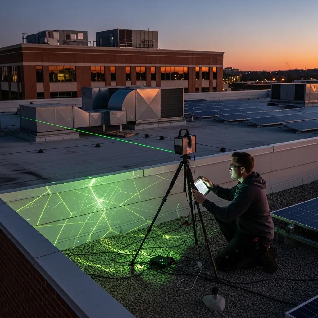
How Does Precision Layout Technology Support Renewable Energy Systems in Buildings?
Precision layout technology converts coordinated digital models into millimeter‑accurate field placements, closing the loop between BIM/VDC and the built environment. Tools include Robotic Total Stations (Trimble), GNSS/RTK for open sites, laser templates, and 3D‑printed guides for prefabricated assemblies. The workflow—export model → stake from the model with robotic instruments → verify with scans—minimizes on‑site adjustments and ensures anchors, racks, and conduits land exactly where the model specifies. That accuracy cuts rework, reduces material waste, and improves electrical routing—directly shortening commissioning timelines and protecting system performance. Comparing layout approaches clarifies trade‑offs in accuracy, speed, and tolerance for renewable installs.
Introductory comparison of layout approaches and expected impacts is shown in the table below.
| Layout Approach | Characteristic | Impact on Rework |
|---|---|---|
| Robotic Total Station | Model‑driven, millimeter‑level accuracy | Minimizes anchor and conduit misplacements |
| Manual Layout | Tape‑and‑transit methods | Greater tolerance variability; more rework |
| GNSS/RTK | Fast site staking for open areas | Good for large ground arrays; limited rooftop use |
What Is the Impact of Robotic Total Station Layout on Solar Panel Accuracy?
Robotic total station layout transfers BIM coordinates to the field to place anchors, racking lines, and penetrations with millimeter to sub‑centimeter precision—preserving array alignment and tilt. The method exports coordinates to the robotic system, stakes points on site, then validates placements with quick verification scans; this prevents cumulative placement error that can reduce array performance. Accurate anchor placement reduces structural remediation, keeps module rows aligned for efficient stringing, and minimizes conduit bends and extra fittings. Measurable results include fewer punch‑list items, shorter commissioning checks, and reduced labor for alignment corrections—helping the as‑built match the energy assumptions used in simulations.
How Does 3D Scanning Aid in Retrofitting Buildings for Renewable Energy?
3D laser scanning captures accurate as‑built geometry of rooftops, facades, and subsurface corridors to produce point clouds for scan‑to‑BIM workflows. The sequence—field scanning → point cloud registration → model reconciliation—reveals obstructions, penetrations, and surface conditions that drawings often miss. For retrofits, scans cut surprises by locating structural penetrations, rooftop equipment conflicts, and cladding details that affect BIPV or rooftop PV. Using 3D scans in coordination enables prefabrication of brackets and conduit runs and reduces mobilization cycles because the field condition is known before crews arrive.
What Are the Key Challenges in Integrating Renewable Energy into Sustainable Buildings?
Adding renewables to buildings introduces technical, logistical, regulatory, and coordination challenges that are best addressed early to avoid costly late changes. Technical constraints—structural capacity, roof condition, and penetrations—affect siting and mounting. Logistical issues—sequencing, equipment access, crane or bore rig coordination—can conflict with other trades. Regulatory hurdles—permitting and utility interconnection—vary by jurisdiction and can delay schedules. Coordination breakdowns across disciplines amplify these risks, leading to RFIs, schedule slips, and higher contingency spend. Pragmatic mitigations—structured coordination, early site verification, and integrated documentation—materially reduce risk and protect performance expectations.
- Coordination Risk: Late model convergence leads to clashes; mitigate with regular VDC/BIM coordination meetings and clear RACI matrices.
- Structural Constraints: Delayed structural review slows mount approvals; mitigate with early structural assessments and load‑path modeling.
- Permitting and Interconnection: Regulatory delays derail timelines; mitigate by engaging utilities early and preparing permit‑ready documentation.
A disciplined coordination approach addresses these risks and primes the project for precise field execution.
How Can Coordination Mitigate Risks in Multi-Trade Renewable Energy Installations?
Coordination reduces multi‑trade risk by establishing a repeatable cadence of model‑based meetings, documented responsibility matrices, and milestone deliverables that align trades on sequencing and tolerances. The practice ties model updates to procurement and prefabrication windows so each trade knows when to deliver accurate information. Practical measures include a coordination checklist, scheduled meetings at design milestones, and sign‑offs for key deliverables like penetration schedules and mounting details. These steps clarify ownership at interfaces and create traceable decisions that prevent late rework and disputes.
What Are Common Pitfalls in Renewable Energy System Layout and How to Avoid Them?
Common pitfalls include misplaced rooftop penetrations, inadequate structural review for wind or panel loads, and under‑coordinated electrical routing that forces field changes during stringing. Avoidance centers on pre‑construction surveys, scan‑to‑BIM validation, and robotic verification so field conditions match model expectations. Concrete actions: require structural sign‑off for rooftop arrays, perform 3D scans before ordering custom mounts, and use robotic layout to place anchors to model coordinates. These steps limit late corrections, protect warranties, and keep installations within engineered tolerances to preserve predicted energy performance.
How Can CCLS’s Expertise Drive Efficiency and Cost Savings in Green Building Projects?
Conway Coordination and Layout Services (CCLS) provides digital‑to‑field services—VDC, BIM coordination, 3D scanning, point cloud rendering, and Trimble robotic total station layout—that translate coordination work into measurable schedule and cost savings on renewable projects. The approach combines early digital clash detection with precise field verification to close the gap between design intent and as‑built outcomes—reducing RFIs, change orders, and installation rework. For owners and contractors, that predictability accelerates procurement and prefabrication while verified layouts lower contingency use during commissioning. As a family‑run business led by Nathan Conway, CCLS emphasizes collaborative partnerships and dependable coordination to deliver efficient, reliable renewable installations.
CCLS creates project efficiencies in three core ways:
- Early clash detection and digital twin models reduce RFIs and downstream change orders.
- Precise robotic layout minimizes rework by ensuring anchors and conduits match BIM coordinates.
- Scan‑to‑BIM verification speeds commissioning by validating as‑built conditions before energization.
These services align project teams around a single source of truth and drive measurable improvements in schedule and cost performance.
What Are the Advantages of Early Clash Detection and Digital Twin Models?
Resolving model conflicts during design is far less expensive than fixing them in the field. Digital twin models extend that advantage by delivering a verified as‑built dataset for operations. The savings mechanism is iterative: remove clashes in the model, then hand off a validated digital twin for commissioning, procurement, and O&M reference. Quantifiable outcomes include fewer on‑site fixes, reduced fabrication errors, and clearer procurement specs that shorten lead times. A digital twin is best handed off after construction QA so operations teams inherit an accurate record of installed renewable assets and their metadata.
How Does Precision Coordination Reduce Rework and Accelerate Project Timelines?
Precision coordination minimizes rework by driving layout, prefabrication, and installation from the same coordinated model, shrinking mismatches between shop work and field conditions. Pairing model‑driven layout with robotic staking and verification scans eliminates iterative adjustments and repeat visits. Workflows that use these techniques need fewer RFIs, shorten punch‑list cycles, and compress commissioning windows because installations are correct the first time. For project timelines, this means faster commissioning, fewer labor hours for corrections, and better alignment with occupancy or handover milestones.
What Are Practical Applications of CCLS Services in Renewable Energy Building Projects?
CCLS services apply directly to common renewable applications—BIPV, commercial rooftop solar, geothermal loops, small wind foundations, and retrofits—by providing the digital coordination and field‑accurate layout needed for reliable installation. VDC and BIM coordinate multi‑discipline interfaces, 3D scanning documents as‑built conditions for retrofit planning, and robotic total station layout executes millimeter‑accurate placements for anchors and conduits.
Below is a practical mapping of services to outcomes to clarify benefits and efficiencies when these services are used together.
| Service | Application | Expected Outcome |
|---|---|---|
| VDC / BIM Coordination | BIPV and rooftop arrays | Fewer clashes, more prefabrication, clearer sequencing |
| 3D Scanning / Point Cloud | Retrofit PV and geothermal routing | Fewer surprises, accurate retrofit models, reduced field adjustments |
| Robotic Total Station Layout | Anchor placement and conduit routing | Higher placement accuracy, fewer punch‑list items, faster commissioning |
How Is BIM Used for Building-Integrated Photovoltaics Layout and Coordination?
For BIPV, BIM ties cladding, structural elements, electrical routing, and aesthetic requirements into a single federated model. The workflow authors facade and PV geometry together, validates structural attachment points, and coordinates electrical routing with interior panels and metering. BIM supports prefabrication of mounting assemblies and integrated raceways, reducing on‑site assembly time and preserving architectural intent.
Using BIM to visualize trade‑offs between performance and aesthetics helps stakeholders balance energy yield, maintenance access, and facade design.
What Are Best Practices for Geothermal Heat Pump and Ground Loop Field Design?
Best practices start with integrating geotechnical data, bore sequencing, and utility coordination into VDC models so bore locations and access are optimized before mobilization. Reliable installation depends on collaboration among geotech, civil, and VDC teams to set bore tolerances, sequence drilling, and plan spoil handling. Field verification steps include using layout tools and scan references to confirm bore collars and pipe runs match the model, plus post‑installation tolerance checks to ensure loop integrity. These steps reduce remediation and help ground loop performance meet the assumptions used in energy modeling.
When teams are ready to convert coordinated models into precise field results, Conway Coordination and Layout Services (CCLS) offers consultation and execution for VDC, BIM coordination, 3D scanning, point cloud rendering, and robotic total station layout. To request a consultation, contact Conway Coordination and Layout Services (CCLS) and ask for Nathan Conway.
Frequently Asked Questions
What are the key advantages of using 3D scanning in renewable energy projects?
3D scanning produces an accurate representation of existing conditions, which is essential for retrofit projects. By capturing rooftop and facade geometry in detail, scans reveal obstructions and structural issues that drawings may miss. Point clouds integrate into BIM workflows, enabling better planning and fewer surprises on site. In short, scanning improves execution accuracy and reduces costly rework.
How can early engagement with utilities streamline renewable energy projects?
Engaging utilities early clarifies interconnection requirements, permitting steps, and potential grid impacts—details that vary by jurisdiction. Addressing these items up front avoids surprises, keeps schedules on track, and increases the chance of a smooth commissioning process. Early utility coordination is a low‑risk, high‑value activity for any renewable project.
What role does lifecycle management play in renewable energy systems?
Lifecycle management keeps systems performing over the long term. It includes monitoring, scheduled maintenance, and data analysis from installation through operation. Effective lifecycle practices—asset tagging, service intervals, and documented warranties—help owners maximize yield, extend asset life, and lower operating costs.
How does precision layout technology impact project costs?
Precision layout tools, like robotic total stations, reduce rework and material waste by ensuring millimeter‑level placement accuracy. That accuracy cuts errors from misalignment or incorrect placements, reduces change orders and RFIs, and speeds installation. The upfront investment in precision layout typically pays off through lower overall project costs and more predictable outcomes.
What are the benefits of integrating VDC and BIM in renewable energy projects?
Combining VDC and BIM improves collaboration across disciplines, enables early clash detection and resolution, and reduces delays and rework. VDC provides the sequencing and coordination framework while BIM supplies the data and simulations for sizing and lifecycle planning. Together they streamline workflows, improve accuracy, and increase the likelihood of completing projects on time and on budget.
What challenges do teams face when retrofitting buildings for renewable energy?
Retrofitting brings structural constraints, legacy building conditions, and evolving code requirements that can complicate installation. Conflicts between existing systems and new equipment can increase costs and cause delays. Accurate assessment of as‑built conditions is vital—advanced planning, clear communication, and tools like 3D scanning and BIM mitigate these risks.
Conclusion
Integrating renewable energy into buildings with precision coordination and digital tools improves outcomes and reduces cost and schedule risk. By combining VDC, BIM, and precision layout technologies, project teams can deliver installations that meet performance goals with less rework. The true value is predictability—faster procurement and commissioning, fewer surprises, and clearer handoffs to operations. To discuss how CCLS can support your next renewable project, contact us today.