
Optimized BIM-Based Layout Planning for Construction: Precision, Efficiency, and Project Success
BIM-based layout planning ties the digital model directly to field work so teams hit tolerances, follow predictable sequences, and cut rework. This guide shows how BIM becomes the single source of truth for layout points, how VDC consulting overlays schedule and logistics onto models, and how robotic total stations plus 3D point-cloud verification close the loop between model and site. You’ll get practical model-to-field workflows, an explanation of clash detection and 4D simulation in pre-construction, and examples of where these methods deliver the best ROI. We also review key technology choices — from Trimble robotic surveying systems to 3D scanning and AI-assisted clash detection — and offer checklists for coordination meetings and quality assurance. Measurable benefit categories and an EAV-style comparison help owners and contractors quantify cost, schedule, and rework impacts and decide when to bring in specialists like Conway Coordination and Layout Services (CCLS). The next section defines BIM-based layout planning and highlights the core benefits that drive adoption.
What is BIM-Based Layout Planning and Why is it Essential for Construction?
BIM-based layout planning extracts coordinates and construction intent from a federated model to produce stakeout points, layout control, and installation tolerances used on-site. In practice, the model-to-field workflow turns design elements — structural grids, MEP runs, equipment pads — into precise layout deliverables for stakeout and verification. The payoff is tighter tolerance control, fewer on-site clashes, and more accurate sequencing that supports prefabrication and safer logistics. Understanding this foundational workflow explains why BIM layout planning is now central to modern pre-construction and digital construction practices.
BIM layout planning connects several discrete activities into a measurable workflow:
- Extracting model coordinates and validating them for field transfer.
- Detecting and resolving clashes before installation starts.
- Performing stakeout and verification tied to as-built documentation.
These steps reduce ambiguity between design and execution and set the stage for VDC services that add time sequencing and site simulation.
On real projects, specialist teams handle model prep, stakeout, and scan-to-model integration. As an example, Conway Coordination and Layout Services (CCLS) is a family-owned firm that provides BIM modeling and coordination, VDC consulting, 3D scanning, and robotic total station layout across the Southeast U.S., turning these workflows into repeatable field results.
Defining Building Information Modeling and Its Role in Layout Planning
Building Information Modeling (BIM) is the digital representation of a facility that carries geometry, metadata, and relationships for every element. It serves as the authoritative dataset from which layout points and control geometry are derived. Elements like columns, MEP centerlines, and equipment pads hold coordinates, tolerance bands, and level data that feed stakeout files and fabrication drawings. Federated models combine discipline-specific authoring files (for example, Revit exports) into a single coordinated dataset so clash detection can surface issues that would otherwise appear in the field. Validating coordinate systems, baselines, and control points in the model before export is essential so robotic survey gear and layout crews can stake points with confidence and traceability to design intent.
Because accurate coordinates reduce variation between shop and field, BIM becomes the hub for downstream processes like prefabrication and sequencing. Preserving interoperability with field equipment and file formats keeps model fidelity intact during handoff to stakeout and 3D-scan verification workflows.
How BIM Improves Construction Site Layout Optimization
BIM improves site layout by revealing spatial conflicts early, supporting prefabrication planning, and enabling construction-sequence simulation to test site logistics. Clash detection analyzes the federated model to find hard and soft clashes and helps prioritize fixes by schedule and constructability impact. Coupled with 4D simulation, teams can visualize installation order, crane access, and material staging to cut congestion and rework. A better layout supports offsite fabrication tolerances, reduces field adjustments, shortens installation time, and tightens QA procedures.
Optimized layout planning also lets teams iterate site logistics—placing temporary works and access routes in the model—so sequencing becomes safer and more efficient on day one.
How Does Virtual Design and Construction Consulting Enhance Project Coordination?

VDC consulting applies model-based practices, 4D sequencing, and coordination workflows to translate BIM into executable schedules and field actions. VDC bridges design intent and construction sequencing by delivering federated models, time-linked schedule models, and clear coordination outputs that align procurement, prefabrication, and site activities. At its core, VDC reduces uncertainty and speeds decisions through visual simulations and data-driven coordination, making sequencing more predictable and lowering downstream risk. Effective VDC also defines roles, deliverables, and meeting cadence so model authors, contractors, and trade partners collaborate with clarity.
VDC deliverables commonly include artifacts and processes that directly feed layout planning and stakeholder alignment:
- Federated model exports with clash reports and prioritized issue lists.
- 4D construction simulations tied to schedule logic for visual sequencing.
- Coordination meeting records and tracked action items for trade teams.
These deliverables make sure layout points and stakeout priorities line up with schedule milestones and procurement windows, smoothing the handoff to field stakeout and robotic layout operations.
Understanding VDC Consulting Services and Their Benefits
VDC consulting covers model federation, 4D simulation, coordination management, and field-data integration to boost predictability and lower risk. Consultants ready federated models for clash detection, tag coordination issues with responsibility and timelines, and simulate installation sequences to validate constructability and crane access. The result for project teams is clearer scope, earlier conflict resolution, and improved sequencing that supports prefabrication and steadies labor demands. VDC also accelerates stakeholder alignment by producing visual artifacts that make schedule impacts and spatial constraints tangible for non-technical decision makers.
These services reduce surprises in construction and put the next phase—field stakeout and verification—on a more deterministic path by mapping model-based points to scheduled activities.
Integrating VDC with BIM for Seamless Construction Sequencing
When VDC and BIM are integrated, model authoring, federation, schedule import, and layout extraction form a continuous thread from design through installation. A typical workflow is: model authoring in discipline tools → federated coordination model → 4D schedule import for time-linked sequences → extract layout points and stakeout files → field verification and as-built scanning. Schedule importers and model-based sequencers tie each layout action to milestones and crew assignments. That alignment closes gaps between schedule assumptions and field reality, enabling more accurate sequencing and smoother prefabrication handoffs.
Closing the loop with field verification keeps the model faithful to installed conditions and allows sequencing to adapt to real-world constraints.
What Are the Advantages of Using Robotic Total Station Layout in Construction?
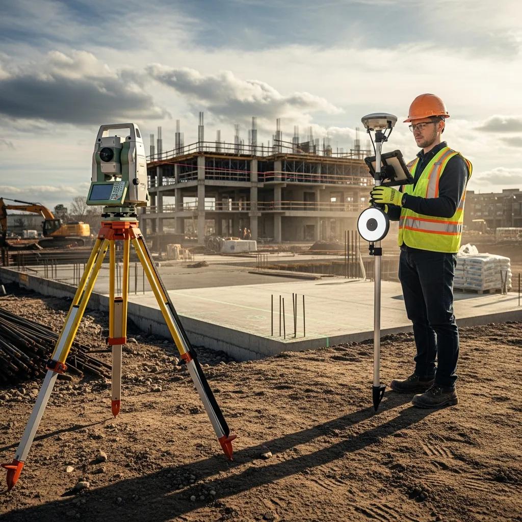
Robotic total stations deliver millimeter-level accuracy, faster stakeout cycles, and repeatable results that outperform manual layout. They automate targeting, enable single-operator workflows, and integrate with model coordinates to cut transcription errors. Practically, robotic layout reduces stakeout labor hours, lowers the volume of layout RFIs, and raises confidence in prefabrication interfaces. As part of a model-to-field workflow, robotic systems improve traceability because stakeout logs and measurement records can be compared directly to the federated model.
Below we outline typical layout approaches and where robotic systems add the most value.
The next subsection explains how Trimble systems deliver the accuracy and data integration needed for model-driven stakeout.
Ensuring Millimeter Precision with Trimble Robotic Total Station Technology
Trimble robotic total stations combine automated tracking, precise angular measurement, and reliable distance meters to transfer BIM coordinates to physical control points with repeatability. Features like robotic targeting and prism tracking allow a single operator to run complex stakeout sequences while staying aligned to project baselines. Typical data workflows use exported stakeout files from federated models and include QA checks like control-point verification and re-stakes to confirm tolerances. Those QA steps close the loop by comparing as-built scan points to original model coordinates, verifying the stakeout met design intent.
Using Trimble equipment in a structured model-to-field process reduces human error and shortens the time between layout plan and verified installation, which supports prefabrication accuracy and schedule reliability.
Comparing Robotic Layout Methods to Traditional Construction Layout
Robotic total stations differ from traditional manual layout in accuracy, speed, labor needs, and rework risk; in most complex projects, robotic methods show clear operational advantages. Robotic workflows offer sub-centimeter accuracy, faster point-by-point stakeout, single-operator operation, and digital QA records. Traditional methods rely on multi-person transit and manual chalking or stringing, which increases variability. The table below summarizes attributes and use cases to help teams choose the right approach for project complexity and tolerance requirements.
| Layout Method | Accuracy | Typical Use Cases |
|---|---|---|
| Robotic Total Station | Sub-centimeter to millimeter repeatability with digital record-keeping | High-tolerance MEP placement, prefabrication interfaces, heavy-equipment alignment |
| Traditional Manual Layout | Centimeter-level accuracy, higher labor intensity | Simple foundations, small renovations, low-tolerance installs |
| Laser/Total Station Hybrid | High accuracy with line visualization, moderate automation | Long-run alignment, façade systems, tunnel/linear works |
The comparison shows robotic methods are preferable where precision and documentation matter most, while manual methods still fit low-complexity tasks. Moving to robotic workflows reduces rework and supports model-driven quality control.
How Does BIM Coordination Improve Construction Project Outcomes?
BIM coordination streamlines federation, clash detection, and resolution so field conflicts are reduced and schedules stay on track. A coordinated federated model centralizes geometry from discipline models and enables prioritized clash detection that targets the highest-impact issues first. Coordination processes assign responsibilities to general contractors, trade partners, and model authors and produce action lists and revised model versions that reflect resolved issues. Disciplined BIM coordination reduces on-site surprises, improves sequencing reliability, and smooths handover to commissioning and O&M phases.
The subsections that follow break down coordination workflows and show how automated clash detection lowers rework risk.
Key Processes in BIM Coordination for Construction Teams
Core BIM coordination tasks include building a federated model, running clash detection, prioritizing collisions by constructability impact, and managing resolutions through a structured meeting cadence. Model QA checks element classification, levels, and tolerances before reporting clashes so the findings reflect real conflicts, not data errors. Coordination meetings should produce documented outcomes: assigned actions, updated model submissions, and verification steps linked to the schedule. These structured processes turn model findings into actionable field tasks and improve the predictability of construction sequencing.
Applying these processes consistently builds a continuous improvement loop: resolved clashes reduce similar issues down the line and help refine prefabrication tolerances.
Reducing Errors and Rework through Advanced Clash Detection
Advanced clash detection combines rule-based checks, prioritized reporting, and AI-assisted grouping to cut noise and focus teams on high-risk interferences that trigger costly rework. Clashes — whether hard geometry intersections, clearance violations, or sequencing conflicts — are triaged so teams protect long-lead items and critical-path activities first. Automation speeds report generation and can suggest likely responsible disciplines, while manual review preserves constructability judgment. Resolving priority clashes in pre-construction or early construction prevents many field reworks and helps keep schedules intact.
These capabilities link tightly with 4D scheduling so clash resolution aligns with installation sequences and resource planning.
Which Industry-Specific Applications Benefit Most from Optimized BIM Layout Planning?
Some sectors see especially large returns from optimized BIM layout planning because of tight tolerances, complex equipment, or regulatory demands. Healthcare and pharmaceutical projects require strict MEP coordination and infection-control sequencing; manufacturing and industrial facilities need accurate heavy-equipment placement and process alignment; historic preservation projects rely on high-fidelity as-built documentation for sensitive work; and commercial construction benefits from prefabrication and tight tenant-fit workflows. Tailoring BIM and VDC deliverables to industry constraints ensures layout planning addresses compliance, operational continuity, and long-term facility management. The table below maps industries to key BIM/VDC uses and primary benefits to help teams prioritize services.
| Industry | Key BIM/VDC Use | Primary Benefit |
|---|---|---|
| Healthcare & Pharmaceuticals | Detailed MEP coordination and equipment-room layout | Compliance with tight tolerances and regulatory standards |
| Manufacturing & Industrial | Large-equipment placement and process-flow simulation | Reduced downtime and reliable equipment interfaces |
| Historic Preservation & Renovation | High-fidelity as-built point-cloud integration | Preservation of original conditions and precise retrofit planning |
| Commercial & Industrial Construction | Prefabrication coordination and tenant-fit sequencing | Faster turnover and minimized tenant disruption |
This mapping clarifies how different sectors use BIM layout planning to meet operational and regulatory needs, producing more predictable delivery and smoother handover.
BIM for Healthcare and Pharmaceutical Construction Projects
Healthcare and pharmaceutical projects demand tight spatial and tolerance control for MEP systems, sterile zones, and medical equipment. Precise BIM coordination and layout are essential to meet compliance and patient-safety goals. Model-driven MEP coordination validates routing, clearances, and equipment access before installation and supports infection-control sequencing in critical areas. Handover models with O&M data and as-built verification simplify regulatory inspections and facility operations. These practices reduce costly rework in sensitive environments and shorten the path to clinical occupancy.
Validated coordinates and documented stakeout records support traceability and regulatory audits at turnover.
BIM and VDC in Manufacturing and Industrial Facility Layouts
Manufacturing and industrial sites need accurate machine placement, precise crane and conveyor clearances, and integrated process flows — all areas where BIM and VDC-driven layout planning add value. Prefabricated skids and modular assemblies are checked against model coordinates and simulated installation sequences to ensure fit. Shop drawings and fabrication models are reconciled with the federated BIM to minimize onsite modifications and equipment downtime. This model-centric approach shortens startup timelines and reduces commissioning issues.
Linking shop and fabrication workflows to model-based tolerances prevents costly field adjustments and improves operational readiness.
What Are the Measurable Benefits and ROI of Optimized BIM-Based Layout Planning?
Optimized BIM layout planning produces measurable gains across cost, schedule, quality, and safety — and these can be compared with EAV-style metrics to guide investment choices. Cost savings come from less rework and smarter prefabrication; schedule benefits come from cleaner sequencing and fewer installation delays; error and rework reductions come from prioritized clash resolution and better shop-to-field coordination. Teams should track metrics like rework hours, installation cycle time, and change order frequency to quantify ROI and validate digital-construction improvements. The table below outlines typical benefit categories and practical notes for measurement.
| Metric Category | Measurable Outcome | Notes |
|---|---|---|
| Cost Savings | Fewer change orders and lower rework expenses | Compare pre- and post-coordination change order values |
| Schedule Impact | Time saved on critical-path installations | Measure 4D-simulated versus actual sequence durations |
| Error / Rework Reduction | Fewer field corrections and punch-list items | Use as-built scan comparisons to quantify deviations |
This EAV-style comparison helps stakeholders connect BIM and layout investments to concrete outcomes and build a measurement plan for ROI validation.
Case Studies Demonstrating Cost Savings and Schedule Adherence
Case studies typically follow challenge → solution → outcome to show how coordinated BIM, VDC, and robotic layout practices reduced rework and protected schedules. Project summaries demonstrate how federated models and 4D sequencing uncovered critical clashes before procurement, how robotic stakeout aligned prefabricated components to installation coordinates, and how as-built scanning verified turnover. Providers often publish these summaries; Conway Coordination and Layout Services (CCLS) maintains a portfolio of projects that highlights BIM modeling and coordination, 3D scanning, and robotic total station layout across commercial and industrial work in the Southeast U.S. Reviewing these examples helps teams understand expected results and which metrics to collect on their own projects.
These case summaries point to measurable improvements and lead naturally to a discussion of digital twins and AI.
How Digital Twins and AI Integration Enhance Construction Monitoring
Digital twins extend BIM by connecting the federated model to live project data — schedules, sensor feeds, and scan-based progress — enabling real-time monitoring, early warnings, and lifecycle insights. AI enhances BIM automation by improving clash detection, grouping recurring issues, and predicting likely schedule slippage from historical patterns. Use cases include automated QA that flags out-of-tolerance work from point-cloud comparisons, predictive maintenance alerts driven by sensors, and continuous model updates tied to verified as-built conditions. These capabilities support better decision making during construction and during O&M handover by producing a living model that informs long-term asset performance.
Successful digital-twin and AI projects start with a measurement baseline and consistent data capture so predictive models deliver reliable ROI and actionable monitoring.
When teams are ready to quantify benefits and apply these workflows, Conway Coordination and Layout Services offers consultations and portfolio references to evaluate fit by project type and geography. Talking with a specialist helps turn projected savings into a tailored measurement plan.
- Request a technical consultation to align model deliverables with layout tolerances and measurement plans.
- Define metrics up front — cost, schedule, and rework indicators — so you can validate ROI.
- Pilot model-to-field workflows in a critical area to demonstrate measurable gains before scaling up.
These steps create a practical path from analysis to implementation and ensure BIM layout investments produce verifiable results on your project.
Frequently Asked Questions
1. What are the key differences between BIM and traditional construction methods?
BIM replaces fragmented 2D deliverables with a single, data-rich 3D model that represents both geometry and function. Unlike traditional drawing-driven processes, BIM centralizes information so teams can coordinate, visualize, and resolve issues earlier. The result is improved accuracy, fewer misunderstandings, and less rework because everyone works from the same source of truth.
2. How does clash detection work in BIM, and why is it important?
Clash detection uses software to compare discipline models and find conflicts — for example, where ductwork intersects structure or clearance is insufficient. Detecting and prioritizing those clashes early lets teams resolve them before they show up on-site, which reduces costly rework and schedule delays. When paired with constructability reviews, clash detection directly protects the critical path.
3. What role does 4D simulation play in construction planning?
4D simulation adds time to the 3D model so teams can visualize the build sequence. It helps identify schedule conflicts, optimize resource allocation, and test site logistics like crane access and material staging. By simulating the timeline visually, stakeholders understand how tasks interact and can make better sequencing and procurement decisions.
4. How can BIM improve safety on construction sites?
BIM improves safety by enabling scenario planning and visualization of site logistics before work begins. Teams can model equipment placement, worker flows, and temporary works to identify hazards and plan mitigations. Better coordination and clearer communication about site conditions also help reduce accidents and improve outcomes.
5. What are the benefits of using robotic total stations in construction layout?
Robotic total stations provide higher accuracy, faster stakeout, and better documentation than manual methods. They automate targeting, support single-operator workflows, and integrate with BIM coordinates to reduce transcription errors. The result is improved prefabrication fit, fewer change orders, and a stronger audit trail for layout work.
6. How does VDC consulting contribute to project success?
VDC consulting turns model data into executable construction plans through federation, 4D sequencing, and coordination management. By aligning models with schedule logic and procurement windows, VDC reduces uncertainty, speeds decisions, and improves stakeholder alignment — all of which increase the predictability of construction outcomes.
7. What industries benefit the most from BIM-based layout planning?
Healthcare, manufacturing, historic preservation, and commercial construction often see the largest returns because they have tight tolerances, complex equipment, or regulatory demands. Tailored BIM and VDC deliverables make sure layout planning supports compliance, operational continuity, and long-term facility management.
Conclusion
Optimized BIM-based layout planning raises construction accuracy and efficiency by pairing proven processes with modern tools. Robotic total stations, VDC consulting, and coordinated federation work together to reduce rework, speed sequencing, and improve handover. Specialized providers like Conway Coordination and Layout Services can tailor these solutions to your project and geography, helping you turn model data into reliable field outcomes. Contact us to learn how we can help make your next project more predictable and cost-effective.