Point Cloud Rendering & BIM Integration — Columbia, SC: Services, Workflow, and Project Benefits
Point cloud rendering and BIM integration turn dense 3D scan data into reliable, usable models that simplify construction, renovation, and facility-management work in Columbia, SC. This guide defines point cloud rendering, shows how reality-capture tools like 3D laser scanners and LiDAR feed model-based workflows, and explains why precise point-cloud-to-BIM conversion matters for local projects. You’ll get a clear capture-to-delivery pipeline, an overview of the technologies and QA practices that produce trustworthy as-built documentation, and practical benefits—less rework, earlier clash detection, and better prefabrication. We also cover industry-specific uses for healthcare, industrial, commercial, and historic preservation work, and show how digital-twin strategies extend scan-derived BIM into operations. A concise FAQ and onboarding checklist help Columbia project teams plan capture windows, realistic schedules, and clear deliverables.
What is Point Cloud Rendering and How Does It Support Construction in Columbia, SC?
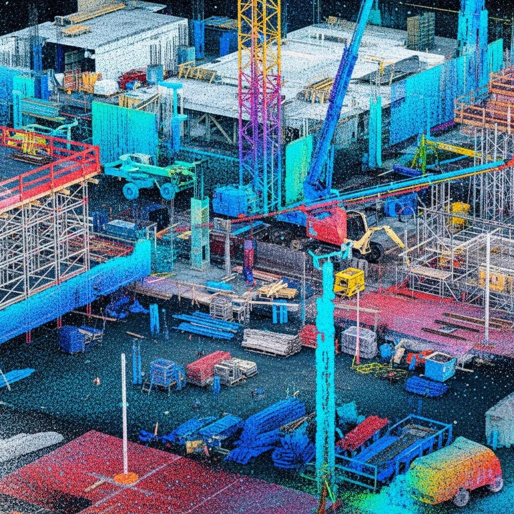
Point cloud rendering visualizes registered 3D scan points from a site so designers, contractors, and owners can confirm existing conditions, measure deviations, and build accurate base models for design and construction. It combines dense spatial coordinates from terrestrial scanners or drone LiDAR with software that produces TruViews, textured meshes, or navigable point-cloud viewers—an immediate visual record of as-built conditions. The practical upside: teams verify dimensions, catch clashes before field work, and reduce the schedule delays and costly rework that come from unknown conditions. In Columbia—where renovations, campus upgrades, and industrial retrofits are common—rendered point clouds shape design decisions and make coordination meetings data-driven and focused on constructability. Knowing capture methods and handoff deliverables helps teams request the right level of detail for their downstream BIM needs.
Understanding 3D Laser Scanning and Point Cloud Data Capture
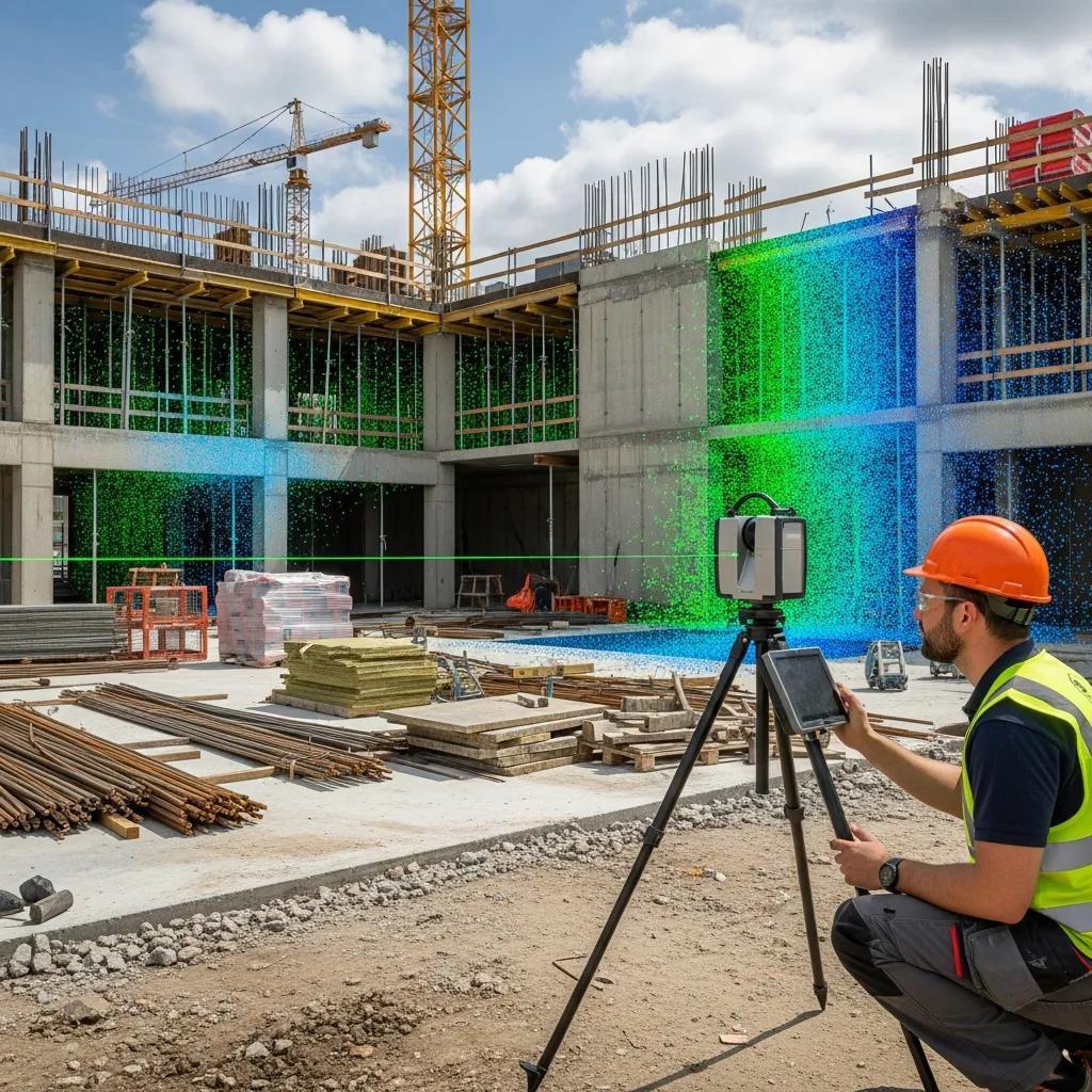
3D laser scanning records millions of spatial points by timing laser returns from surfaces, producing dense point clouds that represent geometry and surface reflectivity across complex sites. Terrestrial scanners are best for interiors and façade details; drone-mounted LiDAR is efficient for exterior topography and roof geometry. Both approaches rely on a control strategy—targets, GNSS, or cloud-to-cloud registration—to guarantee spatial accuracy. Typical best practices include establishing control, scanning with adequate overlap, using registration targets where needed, and capturing supplemental imagery for textured outputs. Accuracy depends on instrument class and workflow: high-resolution terrestrial scanners and robotic total stations deliver the fidelity required for tight-tolerance MEP and structural coordination. These capture fundamentals feed directly into converting raw scans into structured BIM assets ready for construction use.
How Point Cloud Data Converts into BIM Models for Precise Project Execution
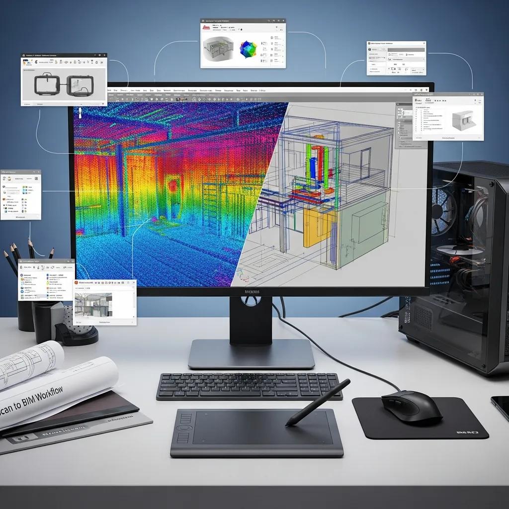
Scan-to-BIM converts raw point clouds into semantic, parametric BIM models by segmenting geometry, classifying elements, and modeling to agreed Levels of Detail and reliability for construction. Typical steps include registration, noise filtering, classification of structural and MEP components, model authoring in Revit (or similar), and validation against the point cloud with deviation analysis and QA checkpoints. Clients should specify LOD—LOD 200 for coordination or LOD 300–350 for fabrication/prefab—so modelers build families and constrained geometry suitable for clash detection and shop production. QA checks such as section comparisons, point-to-surface deviation reports, and federated model reviews confirm the BIM represents the as-built condition before handoff to estimating, VDC coordination, or shop drawings. Clear deliverable lists and acceptance criteria remove ambiguity and support precise field execution.
How Does CCLS Deliver Accurate Point Cloud to BIM Conversion Services?
Point cloud to BIM conversion needs a structured workflow, precision instruments, and quality-control gates to produce models that integrate with construction teams’ processes. Conway Coordination and Layout Services (CCLS) focuses on precision layout and model interoperability to reduce rework and streamline coordination for Columbia’s construction and industrial clients. We combine reality capture with modeled deliverables—registered point clouds, validated Revit models, and clash-ready federated files for VDC reviews. If you’re ready to move from scans to coordinated models, schedule a consultation with Conway Coordination and Layout Services to scope capture, define LOD, and set QA acceptance criteria.
- Scope & Control: Agree on deliverables, LOD, and control requirements with project stakeholders.
- Data Capture: Execute terrestrial scanning, targeted LiDAR, or total-station layout to gather site data.
- Processing & Registration: Register scans, remove noise, and georeference data for consistency.
- Modeling: Author parametric BIM elements in Revit to the specified LOD and classification.
- QA/QC & Handoff: Validate models against the point cloud, produce clash reports, and deliver interoperable files.
This five-step workflow aligns conversion work with client schedules and delivers coordination value that reduces RFI-driven delays and improves prefabrication outcomes.
Below is an introductory comparison of common capture instruments and typical deliverables to help teams choose the right approach for their project.
| Tool | Characteristic | Typical Deliverable |
|---|---|---|
| Trimble Robotic Total Station | High-precision layout and survey control; integrates field-to-model checks | Control points, as-built verification reports, layout stake files |
| Terrestrial Laser Scanner | Very high-density interior/exterior geometry capture | Registered point cloud, TruViews, textured meshes |
| LiDAR Drone | Fast exterior coverage and access to hard-to-reach surfaces | Topographic point clouds, orthophotos, roof geometry |
Use this comparison to balance speed and fidelity based on project tolerances and site access conditions.
Technologies Used: Trimble Robotic Total Station and Revit Integration
Reliable layout and model handoffs depend on instrument–software interoperability. Trimble Robotic Total Stations provide field accuracy for staking and model validation, while Revit is the primary authoring environment for BIM deliverables. Robotic total stations enable coordinate-verified staking and quick as-built checks to confirm modeled geometry matches field conditions—critical for tight-tolerance MEP and structural elements. Revit models produced from vetted point clouds can be federated in Navisworks or another coordination platform for clash detection and model review. Best practices include maintaining a coordinated datum and naming conventions, exporting neutral formats when necessary, and providing clear metadata so downstream teams can use models for prefabrication, estimating, and site layout.
Typical tools integrated:
- Trimble Robotic Total Station for precision layout and verification.Revit for BIM authoring and parametric families.Navisworks/Coordination Platforms for clash detection and federated review.
These integrations reduce ambiguity between the field and model and accelerate the move from scanned reality to build-ready documentation.
Step-by-Step Process of Point Cloud Processing and Model Integration
A disciplined processing pipeline turns scans into validated BIM assets through defined steps with QA gates to maintain confidence in deliverables and schedules. The typical five- to seven-step sequence starts with control setup and capture, continues with registration and filtering, moves into classification and modeling, and finishes with QA validation and deliverable assembly. Timelines depend on site size, required LOD, and access: small interiors can close in days; complex industrial sites may need several weeks for capture and modeling. Key checkpoints include point-cloud-to-model deviation analysis, element-level QA, and coordination sessions that produce clash reports and an action log for resolution. Deliverable packages commonly include registered point clouds, Revit models at agreed LOD, clash reports, annotated TruViews, and measured drawings for construction use.
- Establish Control & Plan Capture: Set datum, control points, and access plan.
- Perform Scanning & Data Collection: Capture with the appropriate instruments and coverage.
- Register & Clean Data: Align scans, remove noise, and georeference the dataset.
- Classify & Model: Segment point clouds and author BIM elements to the agreed LOD.
- QA/QC & Deliver: Validate models, produce clash reports, and deliver federated files.
This stepwise approach clarifies responsibilities and produces consistent, verifiable outputs for project teams and subcontractors.
What Are the Key Benefits of Point Cloud Rendering & BIM Integration for Columbia Construction Projects?
Point cloud rendering plus BIM integration delivers measurable benefits: it reduces rework by validating as-built conditions, improves coordination through earlier clash detection, supports prefabrication with precise geometry, and speeds stakeholder decision-making. Converting reality-capture data into coordinated models helps teams cut downstream change orders, shorten RFIs, and tighten procurement. These advantages are especially valuable in Columbia where renovations and tight sites require precision and minimal disruption.
Primary project benefits include:
- Reduced Rework: Accurate as-built models prevent field surprises and limit change orders.
- Improved Coordination: Federated models enable earlier clash detection and clearer trade responsibilities.
- Prefabrication Support: Precise geometry lets off-site fabrication fit with fewer issues.
- Faster Approvals: Clear visual deliverables speed stakeholder sign-offs and permit reviews.
- Operational Handover: Enriched BIM supports facility management and asset tracking after turnover.
Adopting a structured scan-to-BIM approach translates these benefits into shorter schedules, lower rework labor costs, and reduced material waste.
| Benefit | Measurable Outcome | Example Scenario |
|---|---|---|
| Reduced Rework | Fewer change orders; single-digit percentage schedule savings | Detecting MEP clashes before fabrication reduces on-site rework during tenant fit-out |
| Improved Coordination | Faster resolution cycles; fewer RFIs | Federated models resolve spatial conflicts earlier, shortening coordination meetings |
| Prefabrication Support | Higher off-site fit accuracy; material savings | Accurate as-built dimensions let shop-built ductwork fit on first install |
This mapping helps owners and contractors quantify expected improvements when budgeting for reality-capture and modeling.
Reducing Rework and Enhancing Construction Accuracy
As-built verification with point clouds uncovers deviations between design intent and existing conditions before installation, directly reducing downstream rework and costly corrections. Deviation analysis produces color-mapped reports that highlight areas outside tolerance thresholds and guide decisions on remediation or design adjustment. Teams can set acceptance tolerances up front and require corrective action when deviations exceed those limits, avoiding field conflicts during critical installs. The outcome: fewer schedule impacts, lower corrective labor costs, and greater installer confidence in the geometry used for prefabrication. Integrated QA also simplifies contractor acceptance and final turnover sign-offs.
Facilitating Clash Detection and Streamlined VDC Coordination
Point-cloud-derived models feed directly into clash-detection workflows in tools like Navisworks, enabling virtual coordination cycles that resolve spatial conflicts before crews mobilize. Clash reports from federated models list intersecting elements, quantify impacts, and assign responsibility for resolution—making coordination meetings more productive and action-oriented. When scan-based models represent true field conditions, coordination emphasizes constructability rather than chasing unknowns, cutting iterative RFIs and on-site rework. The streamlined VDC process shortens coordination cycles and supports fabrication schedules so prefabricated items match field conditions and MEP sequencing stays on track.
Which Industry-Specific Applications Benefit from Point Cloud Services in Columbia, SC?
Point cloud services are tailored by capture density, model LOD, and deliverable format to meet each industry’s regulatory and operational needs. Historic preservation requires high-resolution, non-invasive capture and annotated deliverables for conservation. Healthcare projects need phased capture and tight scheduling to avoid clinical disruption. Industrial facilities benefit from equipment-level verification and loop-verified coordinates for replacement parts and layout. Commercial construction uses scan-to-BIM for tenant improvements and complex façades. The table below compares industry deliverables to help project teams choose the right scope.
| Industry | Typical Scope | Recommended Deliverables |
|---|---|---|
| Historic Preservation | High-detail documentation of decorative fabric and building geometry | High-resolution point clouds, orthophotos, measured drawings |
| Healthcare | Phased captures scheduled around clinical operations; strict infection-control practices | As-built BIM, phased scan packages, MEP coordination models |
| Industrial/Manufacturing | Equipment layout verification and retrofit planning with verified coordinates | Registered point clouds, CAD overlays, layout stake files |
This comparison clarifies how capture strategy and deliverables vary by sector to meet regulatory, conservation, and operational priorities.
Point Cloud Solutions for Historic Preservation and Renovation
Historic preservation projects need non-invasive, high-detail capture to document geometry, finishes, and deterioration patterns while protecting original fabric. Point clouds provide a forensic record for measured drawings, condition reports, and restoration planning, and let architects and conservators test interventions virtually before physical work begins. Typical preservation deliverables include annotated point clouds, orthophotos, and dimensioned drawings that link historical elements to proposed treatments—preserving institutional knowledge and reducing risk during delicate interventions.
Applications in Healthcare, Industrial, and Commercial Construction
Healthcare teams use scanned as-built models to plan equipment installs and phased renovations with minimal clinical disruption; deliverables target MEP routing and room-level LOD for contractor use. Industrial and manufacturing clients rely on point clouds for equipment verification and retrofit planning, producing CAD overlays and verified coordinate lists for fabrication. Commercial construction leverages scan-to-BIM for tenant improvements, façade remediation, and multi-trade coordination, prioritizing federated models for clash detection and shop-drawing prep. In every sector, the right mix of capture density and modeling rigor reduces risk and supports predictable execution.
If your firm operates in healthcare, industrial, historic preservation, or commercial sectors and needs a tailored plan, request a scoped consultation with Conway Coordination and Layout Services to define deliverables and schedules that respect sector constraints.
How Does Digital Twin Technology Enhance Facility Management Using Point Cloud Data?
Digital twins multiply the value of point cloud–derived BIM by combining accurate geometry with operational data to create living models for maintenance, asset tracking, and performance optimization. The point cloud establishes a precise geometric baseline; BIM adds asset metadata; and IoT sensors supply real-time telemetry. Together these elements let facilities teams move from reactive maintenance to condition-based or predictive programs that reduce downtime and energy waste. For long-term asset stewardship, a digital twin becomes a single source of truth linking physical assets, design intent, and operational history.
- As-built capture: High-fidelity point clouds that reflect current geometry.
- BIM enrichment: Attach asset metadata, manufacturer data, and maintenance schedules.
- Sensor integration: Tie IoT feeds to model geometry to track performance.
- Analytics & workflows: Configure alerts, dashboards, and predictive-maintenance routines.
This checklist describes the technical steps from static as-built data to an interactive operational model that supports facility decision-making.
Creating Real-Time Digital Twins for Ongoing Operations
Converting as-built BIM into a real-time digital twin follows a clear sequence: capture accurate geometry, enrich assets with metadata, and deploy selective sensors tied to operational priorities. Start with scan-derived BIM that models assets and spaces, tag items with identifiers and maintenance metadata, then deploy IoT sensors (temperature, vibration, energy) to feed live data into the twin. Analytics identify trends and trigger maintenance workflows. Use cases include occupancy-driven HVAC control, equipment-health dashboards, and streamlined turnover documentation—each relying on a shared coordinate system and consistent metadata to deliver actionable insights to facilities teams.
Integrating IoT and BIM for Predictive Maintenance and Energy Efficiency
Overlaying IoT telemetry onto a BIM-based digital twin enables predictive maintenance by correlating sensor trends with asset geometry and maintenance history to forecast failures before they occur. Typical sensors include vibration monitors for rotating equipment, temperature and humidity sensors for environmental control, and energy meters for system-level consumption tracking. Analytics translate this data into condition indicators and maintenance triggers. Energy-optimization scenarios use occupancy and load data to adjust systems dynamically, reducing consumption while keeping occupants comfortable and compliant. Measurable benefits include less downtime, longer asset life, and lower utilities—results that justify investment in a calibrated digital-twin strategy.
What Common Questions Do Clients Have About Point Cloud Rendering & Integration?
Teams frequently ask about accuracy, timelines, cost drivers, and how to start a scan-to-BIM engagement. Short, direct answers set expectations and speed decision-making. Below are concise responses that clarify precision levels, typical schedules, and onboarding steps for Columbia projects—helpful for owners and contractors assessing readiness and scope.
- How accurate is 3D point cloud modeling in Columbia, SC?: Accuracy ranges from millimeter- to centimeter-level depending on instrument class and control strategy. Factors include instrument type (terrestrial scanner vs. drone LiDAR), control setup, surface reflectivity, and site conditions. For tight-tolerance architectural and MEP work, terrestrial scanning and robotic total stations with proper control provide the fidelity required for fabrication and layout. Define acceptance criteria at the start so model accuracy matches construction tolerances.
- How do I get started with point cloud to BIM conversion for my project?: Start with a scoping meeting to define deliverables, LOD, access constraints, and schedule. A starter checklist clarifies what owners provide and what the scan team will deliver.
The onboarding checklist below lists practical first steps to prepare a site and scope the work efficiently.
- Site walk & stakeholder alignment: Walk spaces and set expectations for deliverables.
- Define LOD and deliverables: Agree on modeling depth, file formats, and acceptance criteria.
- Schedule & access planning: Coordinate capture windows to minimize operational disruption.
- Sample deliverables & acceptance criteria: Review example outputs and QA metrics up front.
- Budget considerations: Understand cost drivers like area, complexity, and required LOD.
Following this checklist helps the project team assemble information so scan-to-BIM work proceeds smoothly and aligns with contractual and operational constraints.
How Accurate is 3D Point Cloud Modeling in Columbia, SC?
Accuracy depends on capture method, control strategy, and site conditions. Terrestrial scanners and robotic total stations typically achieve millimeter- to sub-centimeter precision suitable for layout and prefabrication. Drone LiDAR offers rapid coverage with slightly lower horizontal/vertical precision but is ideal for topographic mapping and roof geometry. On-site practices—robust control, minimizing reflective surfaces during capture, and redundant registrations—preserve accuracy through processing and modeling. Specify tolerances up front and require point-to-model deviation reports as part of QA so the delivered BIM meets construction or fabrication standards.
How to Get Started with Point Cloud to BIM Conversion for Your Project?
Begin with a focused scope definition: clarify model use cases, required LOD, access constraints, and timeline. Next steps usually include a site reconnaissance to identify control and logistics, followed by a proposal that lists deliverables, milestones, and acceptance criteria. Appoint a single point of contact and schedule initial coordination meetings to align families and parameters with client standards. For Columbia teams ready to initiate a scoped capture and modeling plan, request a consultation with Conway Coordination and Layout Services to define deliverables and a realistic timeline.
For help scoping a project, defining LOD, or scheduling capture in Columbia, request a consultation with Conway Coordination and Layout Services to align deliverables with your construction and operational goals.
Frequently Asked Questions
What types of projects benefit most from point cloud rendering and BIM integration?
Point cloud rendering and BIM integration are especially valuable for renovations, industrial retrofits, and historic-preservation work—projects that require precise documentation of existing conditions. Healthcare projects benefit from phased captures that avoid clinical disruption. Commercial construction uses these tools for tenant improvements and complex façade work. Across these use cases, accurate scan-derived models give all stakeholders the up‑to‑date information they need to coordinate and execute efficiently.
How does point cloud data improve facility management after construction?
Point cloud data becomes the geometric foundation for a digital twin that pairs accurate models with operational data. This allows facilities teams to track asset performance, schedule maintenance, and optimize energy use. When combined with IoT sensors and BIM metadata, teams can shift from reactive to predictive maintenance—reducing downtime and extending asset life. The digital twin serves as a single source of truth linking physical assets to their operational history.
What are the cost factors associated with point cloud to BIM conversion?
Cost depends on site size, complexity, required LOD, and capture technology. Additional expenses may include specialized equipment, software licenses, and skilled modeling resources. Poor initial scoping can add cost through rework or schedule delays, so a clear brief and agreed acceptance criteria help control budget and timeline.
How long does the point cloud to BIM conversion process typically take?
Duration varies by site size, complexity, and LOD. Small interior projects may take a few days; larger industrial sites can require several weeks for capture and modeling. The overall schedule covers capture, registration, modeling, and QA. Clear milestones and expectations at the outset help keep delivery on track.
What quality control measures are implemented during the conversion process?
Quality control includes deviation analysis, element-level QA checks, and coordination sessions that produce clash reports. Regular validation against the point cloud and established acceptance criteria identify and correct issues early, reducing the risk of costly rework and ensuring final deliverables meet project requirements.
Can point cloud data be used for future renovations or expansions?
Yes. Point cloud data provides an accurate, up-to-date record of existing conditions, which is invaluable for future renovations or expansions. It supports design decisions, clash detection, and coordination, helping new installations integrate smoothly with existing structures and minimizing disruption during later projects.
Conclusion
Point cloud rendering and BIM integration deliver clear advantages for Columbia construction projects: less rework, better coordination, and improved prefabrication outcomes. Accurate as-built data streamlines workflows and supports informed decisions that lead to smoother project delivery. If you want to optimize your next project, contact Conway Coordination and Layout Services for a tailored consultation—let us help you move from scans to build-ready models with confidence.