
Precise MEP BIM Modeling for Integrated Systems: Comprehensive Services and Benefits
Precise MEP BIM modeling creates detailed mechanical, electrical, and plumbing models that reflect design intent, installation tolerances, and fabrication requirements for integrated building systems. This guide shows how accuracy in MEP BIM reduces clashes, produces fabrication-ready outputs, and supports downstream workflows like robotic total station layout and scan-to-BIM verification. You’ll find the core deliverables—federated models, clash reports, and LOD-specific shop models—and practical benefits of early coordination, from fewer RFIs to dependable installation sequencing. The guide follows the lifecycle from HVAC and plumbing modeling techniques through multi-trade clash detection and prefabrication support, and it closes with how to request a consultation with a specialist. Key terms such as MEP BIM coordination, HVAC BIM, plumbing BIM, fabrication-ready BIM, 3D scanning, and Trimble Robotic Total Station are used to align technical detail with actionable workflows.
What is Precise MEP BIM Modeling and Why is it Essential for Integrated Systems?
Precise MEP BIM modeling defines systems at the level of detail and tolerance needed to coordinate trades, support prefabrication, and enable accurate field layout. It translates design geometry into federated models that drive clash detection and fabrication outputs. The method is simple in concept: accurate component families, defined clearances, and LOD-aligned geometry allow automated clash runs and create fabrication-ready exports that reduce on-site rework. Primary benefits include earlier detection of spatial conflicts, better procurement accuracy, and faster field installation because the model reflects real installation constraints. Typical deliverables are coordinated Revit models, federated Navisworks checks, clash detection reports, and shop-model exports prepared for fabrication. Recognizing these deliverables clarifies why integrated systems modeling improves predictability and constructability and how MEP BIM strengthens coordination across trades.
The next subsection explains how federated models and workflows directly improve mechanical, electrical, and plumbing coordination.
How Does MEP BIM Modeling Enhance Mechanical, Electrical, and Plumbing Coordination?
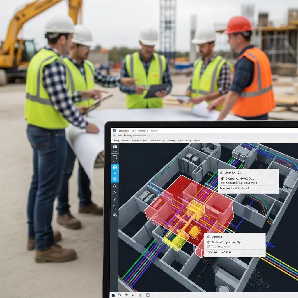
MEP BIM modeling improves coordination by creating a single federated model where mechanical, electrical, and plumbing systems are reviewed together to find and resolve spatial conflicts before construction. Federation enables centralized clash detection, assigns responsibility to specific trades, and tracks resolution with documented changes—reducing ambiguity. For example, a duct reroute found in coordination can be resolved in the model and exported to shop drawings, avoiding costly field changes during installation. This process strengthens communication through annotated clash reports and meeting minutes, results in fewer RFIs, and supports more predictable schedules. Version control and clear documentation ensure clashes stay closed and verified before fabrication or layout begins.
What Technologies Ensure Precision in MEP BIM Modeling?
Achieving precision in MEP BIM depends on a coordinated set of field-capture, modeling, and coordination tools—each producing verifiable geometry and layout instructions. 3D scanning captures point clouds that serve as the as-built reference for scan-to-BIM conversion and preserve real-world tolerances. Revit is used to author LOD 300/350/400 components while Navisworks or similar tools federate models and run clash detection. On-site layout hardware like Trimble Robotic Total Stations converts model coordinates into precise field pick points so anchors and hangers match installed conditions. QA/QC validates model-to-field tolerances and ties elements to fabrication metadata, producing fabrication-ready shop models and reliable layout deliverables. In practice, point-cloud verification informs model updates and layout hardware executes placement with millimeter-level control.
How Does HVAC BIM Modeling Optimize Building Performance and Energy Efficiency?
HVAC BIM modeling improves building performance by enabling accurate system sizing, duct routing, and equipment placement that together enhance airflow and reduce energy loss. The core approach is simulation-informed modeling: engineers use BIM geometry to analyze airflow, pressure loss, and equipment interactions, iterating geometry and components until performance targets are met. Deliverables such as coordinated duct layouts, equipment families, and performance-linked schedules let designers and commissioning agents verify system behavior before installation, cutting redesigns and boosting operational efficiency. Below we compare common HVAC BIM components and show how component-level modeling supports measurable efficiency gains.
Below is a focused comparison of common HVAC BIM components and their modeled outcomes.
| Component | Modeling Attribute | Energy / Airflow Outcome |
|---|---|---|
| Ductwork modeling | LOD 300–350 routing with diameter and insulation | Lower pressure loss and more balanced airflow via optimized routing |
| AHU & equipment families | Performance curves and clearance envelopes | Accurate load matching and easier maintenance access |
| Diffusers & grilles | Placement with throw patterns and CFM assignment | Better occupant comfort and fewer rebalancing cycles |
This comparison shows how component-level modeling links directly to measurable performance improvements and informs commissioning decisions.
When you specify HVAC BIM deliverables, include precise schedules, isometrics, and fabrication-ready exports to bridge design and construction.
What Are the Key Components of HVAC BIM Modeling Services?
Key HVAC BIM deliverables include duct routing with LOD definitions, equipment families for AHUs and pumps, system schedules, and fabrication-ready isometrics. These outputs specify geometry, performance data, and installation clearances so mechanical contractors can prefabricate sections and plan reliable installation sequencing. LOD expectations (for example, LOD 300 for coordination and LOD 350–400 for fabrication) define detail level and metadata, enabling shop drawing exports and CNC-ready outputs. Properly authored families include performance curves and access-space metadata to support commissioning and facility operations. Clear documentation reduces on-site surprises and helps ensure installed systems meet design performance.
Below is a short business-focused callout describing HVAC BIM capabilities from a specialized provider.
Conway Coordination and Layout Services (CCLS) supports HVAC BIM with scan-to-BIM conversion, detailed ductwork coordination, and coordination-ready AHU modeling. Our workflows combine 3D scanning and robotic layout tools to validate clearances and ensure modeled AHUs, VAVs, and duct systems match field conditions and fabrication tolerances.
With deliverables defined, the next subsection explains how HVAC BIM drives airflow improvements and tighter system integration on complex projects.
How Does HVAC BIM Improve Airflow and System Integration?
HVAC BIM improves airflow by enabling simulation-informed routing and clearance checks that reduce turbulence and pressure loss across duct networks. Typical strategies include placing diffusers and balancing devices early in the model, running targeted CFD or airflow checks when needed, and iterating duct sizes and transitions to meet CFM and static pressure goals. Integration checks with structural and architectural models prevent hard clashes and preserve equipment maintenance access, supporting long-term efficiency. In practice, a coordinated model that minimizes abrupt transitions and inefficient runs can lower fan energy use and improve commissioning outcomes. These modeling steps also prepare systems for handover and future digital-twin workflows.
What Plumbing BIM Solutions Support Accurate Water Supply and Drainage Systems?
Plumbing BIM delivers detailed routing, sizing, and coordination for water supply, drainage, and specialty piping so design intent becomes installable, code-compliant systems. The workflow authors pipes and fittings with correct slope, hanger locations, and connection metadata, then federates those models for clash detection and fabrication output. Key deliverables include coordinated pipe routes, isometrics, hanger layouts, and fabrication-ready spool drawings that reduce field adjustments and speed installation. The table below clarifies common plumbing BIM deliverables and their coordination outcomes, followed by a section on medical gas and other specialized systems.
| Deliverable | Coordination Attribute | Fabrication/Installation Outcome |
|---|---|---|
| Drainage & sewer models | Slopes, invert elevations, access points | Fewer reworks and correct inverts at installation |
| Domestic water routing | Pipe sizing, isolation valves, hanger spacing | Reliable pressure/flow performance and smoother commissioning |
| Spool/isometric outputs | Fabrication tolerances and cut lists | Faster prefabrication and reduced field fitting time |
This table underscores how deliverable-level precision turns into installation efficiency and fewer site conflicts.
Next, the subsection explains how BIM handles medical gas and other specialized piping where clearances and compliance are critical.
How Does Plumbing BIM Facilitate Medical Gas and Specialized Piping Systems?
Plumbing BIM models medical gas and specialty piping with exact clearances, dedicated hanger spacing, and zone separation that meet healthcare regulations and maintenance requirements. Treating medical gas as distinct systems in the federated model prevents cross-system clashes and preserves uninterrupted service paths for critical equipment. Coordination includes annotated hangers, test points, and isolation valves required for verification and commissioning in healthcare projects. Accurate plumbing BIM lowers installation risk by enabling prefabricated segments with verified connections and by documenting tolerances needed for field verification and certification. This modeling precision supports facility reliability for patient-safety-critical systems.
As part of plumbing capabilities, the following short business-focused bullet highlights provider experience.
- Conway Coordination and Layout Services (CCLS) : experienced in plumbing BIM for medical gas and specialized piping, combining scan-to-BIM and fabrication-ready isometrics to meet strict healthcare coordination requirements.
What Are the Benefits of Plumbing BIM in Reducing Rework and Enhancing Coordination?
Plumbing BIM cuts rework by identifying clashes and clearance issues before fabrication, which improves schedule reliability and lowers change-order risk. Modeled routes with hanger positions and slope metadata let contractors prefabricate spools and hanger assemblies that fit as intended in the field, minimizing adjustments. Typical outcomes include fewer RFIs, reduced on-site labor hours, and faster commissioning cycles—all translating to cost savings. Coordinated plumbing models shorten the layout-to-installation loop and provide clear fabrication documentation contractors can use directly, reducing measurement errors in the field.
How Does BIM Coordination for MEP Prevent Clashes and Reduce Construction Costs?
BIM coordination for MEP prevents clashes and reduces costs by running a controlled cycle of model federation, clash detection, prioritization, and verified resolution so conflicts never reach the field. The process combines discipline models into a federated environment, runs automated and rule-based clash checks, triages issues by severity, and assigns responsibility to trade partners for model-based fixes. Economically, resolving clashes in the model is far cheaper than fixing them on site; early coordination reduces change orders, labor overruns, and schedule slippage.
The BIM coordination process follows these steps:
- Federate Models : Combine architect, structural, mechanical, electrical, and plumbing models into a single coordination model.
- Run Clash Detection : Execute automated clash checks in federation tools and categorize issues by type and severity.
- Triage and Assign : Prioritize clashes, assign to responsible trades, and document required model changes.
- Resolve & Verify : Implement model changes, re-run clashes, and verify closures before issuing fabrication or layout exports.
This workflow shows how coordinated modeling reduces on-site conflicts and delivers cost savings through earlier resolution. The next subsection compares tools and methods used to detect and manage clashes.
| Coordination Tool | Characteristic | Typical Impact / Resolution Time |
|---|---|---|
| Navisworks clash report | Rule-based automated detection | Quickly identifies geometric clashes; resolution time varies when manual triage is required |
| Model-checking with rulesets | Parametric and rules-driven checks | Prevents systemic errors; speeds resolution for repetitive issues |
| Field verification + point cloud | As-built validation against model | Highest accuracy for late-stage verification; longer validation cycle but reduces rework |
What is the Process of BIM Clash Detection and Multi-Trade Coordination?
Clash detection starts with model federation, continues with scheduled clash runs, and finishes with coordinated resolution managed through trade accountability and version control. Teams typically set a cadence—weekly or biweekly—for clash runs, generate categorized reports, and hold coordination meetings where clashes are triaged by impact and resolved in the originating models. Each closure is tracked with status, an assigned owner, and verification evidence. Cadence and clear ownership shorten the time from detection to verification and guide procurement and fabrication decisions. This structured process keeps models coordination-ready before layout and fabrication begin.
How Does Early Clash Resolution Improve Project Timelines and Budget?
Early clash resolution reduces schedule risk and cost overruns by keeping high-impact issues out of the field and enabling accurate procurement and fabrication planning. Changes found and resolved in the model avoid rework, emergency orders, and extended on-site labor—major drivers of budget increases. Industry experience shows that resolving clashes during design and preconstruction can substantially cut downstream change orders and related costs, improving predictability. The practical outcome is faster installation sequences, smoother commissioning, and lower contingency draws—benefits that also support prefabrication and modular workflows.
What are the Advantages of Integrated BIM Construction for Complex Projects?
Integrated BIM construction links design, fabrication, and field layout into a single coordinated information flow that supports prefabrication, quality control, and lifecycle handover. Using coordinated, LOD-aligned models to drive shop drawing production and layout instructions preserves metadata operations teams can use for digital-twin creation. Industries with complex MEP needs—healthcare, pharma, industrial manufacturing, and historic renovation—benefit most from reduced interference, faster assembly of prefabricated modules, and improved asset documentation. Below are primary prefabrication advantages and how integrated MEP systems enable modular construction with tighter tolerances and reduced cycle times.
- Quality Control : Shop-controlled manufacturing reduces field variability and improves component fit.
- Schedule Acceleration : Parallel fabrication and site preparation shorten overall project timelines.
- Reduced On-Site Labor : Prefabricated assemblies minimize labor demand and improve safety during installation.
How Does Integration of MEP Systems Support Prefabrication and Modular Construction?
Integration supports prefabrication by producing fabrication-ready shop models, clear spooling information, and precise tolerance definitions fabricators use to build modules off-site. The workflow begins with coordinated LOD 350–400 models that include connection points, hanger locations, and fabrication metadata; these models export spools and cut lists that match field interfaces. Tolerance management ensures prefabricated modules align with structural and architectural interfaces at install, reducing fit-up time. Fabrication workflows also see reduced waste and simpler logistics because assemblies are built and staged in controlled environments. This integrated approach improves predictability and quality for modular construction.
What Industry Applications Benefit Most from Integrated MEP BIM Modeling?
Several industries gain outsized value from integrated MEP BIM modeling because of strict coordination needs, specialized systems, or complex workflows. Healthcare and pharmaceuticals require precise medical gas and service routing for compliance and uptime; industrial facilities depend on process piping and equipment integration for safety and reliability; commercial and industrial projects benefit from modular MEP assemblies to accelerate delivery; and historic preservation projects use scan-to-BIM to reconcile as-built conditions with new systems. Each industry uses coordinated MEP models to address domain-specific risks—whether ensuring medical gas continuity in hospitals or enabling accurate retrofits in heritage structures—leading to practical considerations about engaging a coordination provider.
How Can You Request a Consultation for Precise MEP BIM Modeling Services?
Requesting a consultation for precise MEP BIM modeling is straightforward: share project context and key deliverables so a provider can scope modeling, coordination, and layout services. Essential information includes existing design files (Revit/CAD), point cloud data if available, project specifications and target LOD, schedule milestones, and primary coordination contacts. After intake, the provider outlines an initial scope, proposed coordination cadence, expected deliverables (federated models, clash reports, fabrication-ready exports), and an estimated turnaround for the first coordination cycle. The numbered list below shows the practical steps to request a consultation and what to expect during initial engagement.
- Prepare project files : Gather Revit models, CAD drawings, specifications, and any point clouds.
- Define scope and LOD : Specify systems to model and target LOD for coordination or fabrication.
- Submit inquiry : Provide project timeline and primary contacts so the coordination provider can propose an intake plan.
- Receive proposal : Expect a scoped plan with coordination cadence and initial delivery dates.
What Information is Needed to Start an MEP BIM Project with CCLS?
To begin an MEP BIM project with Conway Coordination and Layout Services (CCLS), provide design authoring files (Revit or CAD), any available as-built point clouds, project specifications that define LOD and performance requirements, and contact roles for coordination decisions. Notes on preferred fabrication formats, required isometrics, and specialty systems (for example, medical gas) help scope deliverables accurately. A clear timeline and milestones—procurement dates or erection windows—allow CCLS to prioritize coordination cycles and align clash runs with procurement decisions. Supplying these inputs up front speeds intake and enables precise planning for the first coordination iteration.
What is the Typical Workflow from Design to Fabrication in MEP BIM Modeling?
A typical workflow moves from intake and as-built verification to modeling, federation, clash detection, coordinated resolution, and finally fabrication-ready exports and layout instructions. First, provided models and point clouds are reviewed and any as-built discrepancies noted; then discipline models are authored or refined to the target LOD and metadata requirements. Federation and clash runs follow on a set cadence with resolution tracked and validated; once clashes are closed, shop models and isometrics are generated for fabrication. Final outputs include fabrication metadata, cut lists, and layout coordinates that feed field layout hardware such as robotic total stations for precise installation. This end-to-end loop ensures models move from design intent to verified, installable components.
If your team is ready to start, the next step is to request a consultation with a specialist who can align coordination cadence to project milestones and deliver fabrication-ready BIM outputs.
Frequently Asked Questions
What are the main advantages of using MEP BIM modeling in construction projects?
MEP BIM modeling strengthens collaboration among trades, reduces conflicts, and improves project timelines. A federated model surfaces clashes early in design, minimizing costly rework during construction. MEP BIM also supports accurate prefabrication, speeding installation and improving resource management. Precise modeling contributes to energy efficiency and operational performance, making it a practical tool for modern construction delivery.
How does MEP BIM modeling contribute to sustainability in building design?
MEP BIM contributes to sustainability by improving energy efficiency and reducing waste across a building’s lifecycle. Accurate HVAC, plumbing, and electrical models let teams analyze and simulate energy use to make better design choices. Prefabrication driven by BIM reduces material waste and tightens quality control. These practices lower operational costs and support green building standards and certifications.
What role does clash detection play in MEP BIM modeling?
Clash detection is central to MEP BIM—it finds conflicts between systems before construction. Using automated clash checks on federated models, teams locate issues like overlapping ductwork or piping and resolve them in the model. Early detection and resolution reduce the risk of delays, rework, and cost overruns during construction.
How can MEP BIM modeling improve communication among project stakeholders?
MEP BIM improves stakeholder communication by providing a shared federated model where architects, engineers, and contractors access the same information. This transparency supports better decisions and reduces misunderstandings. Annotated clash reports and meeting notes from coordination sessions offer clear documentation that keeps everyone aligned on progress and changes.
What are the typical deliverables from an MEP BIM modeling project?
Typical deliverables include coordinated Revit models, clash detection reports, fabrication-ready shop drawings, and system schedules. Additional outputs may include isometric drawings, spooling information, and HVAC performance data. These deliverables smooth the transition from design to construction and help teams meet timelines and budgets.
How does MEP BIM modeling support prefabrication in construction?
MEP BIM supports prefabrication by producing fabrication-ready models with accurate dimensions, connection points, and assembly details. With that level of detail, contractors can manufacture components off-site in controlled environments, reducing on-site labor and errors. Prefabrication driven by BIM shortens schedules and improves quality by delivering components built to precise specifications.
Conclusion
Precise MEP BIM modeling improves project efficiency by reducing clashes, sharpening coordination, and enabling accurate prefabrication. By combining proven workflows and modern tools, teams achieve reliable installation and better energy performance, which drives cost savings. Working with a specialized provider ensures tailored solutions and experienced execution. Take the next step toward smoother construction delivery by requesting a consultation today.