
Seamless Point Cloud to BIM Model Conversion Services: Precision and Efficiency for Construction Projects
Turning dense 3D scans into usable BIM is what bridges the field and the model. This guide explains how reality-capture tools — 3D laser scanning and LiDAR — feed into Autodesk Revit and other BIM platforms to produce reliable as-built models for coordination, clash detection, and facilities handover. You’ll get a clear view of what point cloud data contains, the technical steps in a typical scan-to-BIM workflow, practical tools and QA practices, and industry applications from healthcare to historic preservation. We also cover common pitfalls — noise, coordinate mismatches, and LOD decisions — and pragmatic ways to protect accuracy. Finally, we summarize service options and what to look for when choosing a provider that can deliver fabrication-ready and integration-ready models. Keywords such as point cloud to BIM, 3D scan to model, scan to BIM process, and Revit point cloud modeling are used throughout to connect guidance with real project needs.
What is Point Cloud to BIM Conversion and Why is it Essential?
Point cloud to BIM conversion turns raw spatial captures — millions of XYZ points from laser scanners or LiDAR — into structured Building Information Models with geometry, metadata, and an agreed Level of Detail (LOD). The process registers multiple scans to a control system, filters noise, classifies surfaces, and models elements in BIM software so they reflect true as-built conditions. Delivered correctly, as-built BIM reduces field surprises, supports clash detection, and becomes a reliable digital twin for operations. In short, point cloud to BIM closes the loop between reality capture and digital construction, enabling precise coordination and measurement-driven decisions both on site and during preconstruction.
How Does Point Cloud Data Represent As-Built Conditions?
Point clouds represent as-built conditions as discrete X, Y, Z points, often with intensity or color values that hint at material and surface texture. Fidelity depends on point density and scanner accuracy: high density captures thin MEP runs and fine architectural detail; lower density still captures bulk geometry like slabs and structure. Common exchange formats include LAS, E57, and software-specific bundles such as RCP/RCS for ReCap workflows. Consistent coordinate control — tied to survey targets or total station references — is essential to place models correctly. Knowing how density, coordinate systems, and metadata affect modeling fidelity is key when you define LOD and tolerances for as-built deliverables.
What are the Key Benefits of Converting Point Clouds into BIM Models?
Converting point clouds into BIM turns raw reality capture into usable digital assets that drive measurable value across design, construction, and operations.
- Improved Accuracy and Reduced Rework: As-built BIM verifies component locations before fabrication, cutting dimensional errors and onsite misfits.
- Faster Coordination and Clash Detection: Scan-derived models speed interdisciplinary coordination, reduce RFIs, and shorten resolution cycles.
- Better Documentation for Facility Management: Models include metadata and LOD that support maintenance planning and asset tracking throughout a building’s life.
- Cost and Time Savings: Early conflict detection and verified dimensions lower change-order costs and help keep schedules on track.
- Enables Digital Twin and Renovation Planning: High-fidelity models form the baseline for future retrofits, performance monitoring, and digital-twin initiatives.
The table below maps these benefits to practical outcomes so project teams can prioritize what matters most for their scope.
| Benefit Category | Key Attribute | Typical Outcome |
|---|---|---|
| Accuracy | Dimensional verification against survey control | Reduced field rework and fewer RFIs |
| Coordination | Clash detection readiness | Faster coordination cycles and reduced delays |
| Documentation | LOD and metadata inclusion | Improved FM handover and asset management |
| Cost/time | Early conflict identification | Lower change-order costs and shorter schedules |
| Future-use | Digital twin enablement | Easier retrofits and performance monitoring |
This comparison highlights how converting point clouds into BIM delivers concrete time and cost benefits and clarifies decisions when selecting a scan-to-BIM workflow and provider. For teams that need precise capture and efficient model delivery, Conway Coordination and Layout Services (CCLS) centers its capabilities on survey-grade capture, VDC-oriented workflows, and hands-on coordination. We emphasize precision instruments and processes designed to shorten coordination cycles and protect project schedules; contact us for a consultation to align scope and deliverable expectations.
How Does the Scan to BIM Workflow Ensure Accuracy and Efficiency?
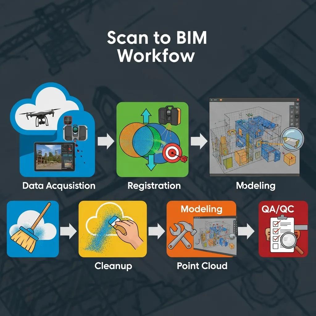
A disciplined scan-to-BIM workflow follows repeatable stages — capture, registration, cleanup/classification, modeling to LOD, QA/QC, and deliverable handoff — to protect accuracy and accelerate downstream use of the model. Each stage uses specific tools and validation checks so teams can predict quality and integrate models into coordination workflows. Tight QA checkpoints at registration and modeling prevent drift from survey control; automation speeds classification, while human review resolves complex MEP and architectural conditions.
Below is a concise, step-by-step summary of the typical scan to BIM workflow:
- Data acquisition and control: Establish coordinate control, place targets, and acquire overlapping scans at the right density.
- Registration and alignment: Use target-based or cloud-to-cloud registration to assemble a unified point cloud within verified tolerances.
- Cleanup and classification: Filter noise, classify surfaces, and segment entities to streamline modeling.
- BIM modeling to specified LOD: Convert classified geometry into parametric Revit families or modeled solids at the agreed LOD.
- QA/QC and deliverables: Validate the model against the point cloud and survey measurements, then produce coordinated delivery packages for handoff.
This structured approach makes the reality-capture workflow auditable, predictable, and easier to integrate with downstream construction processes.
| Stage | Tools / QA Methods | Expected Outcome |
|---|---|---|
| Capture | Terrestrial LiDAR, mobile LiDAR, survey targets | High-density as-built point cloud with control |
| Registration | Cyclone/ReCap algorithms, control checks | Aligned unified point cloud within tolerance |
| Cleanup | Classification tools, manual editing | Filtered dataset ready for modeling |
| Modeling | Revit, Navisworks, scripting tools | Parametric BIM at specified LOD |
| QA/Handoff | Spatial comparison, coordinate checks | Verified deliverables and handoff package |
The table ties each workflow stage to the tools and outcomes you should expect, clarifying choices about tolerances and deliverable scope. In practice, combining automated classification with manual verification produces both accuracy and efficiency when converting point clouds to BIM.
Which Specialized Point Cloud to BIM Services Does CCLS Offer?
Conway Coordination and Layout Services delivers a full suite of services across the reality-capture lifecycle — from high-precision scanning to coordination-ready BIM models and VDC consulting. Our services support teams that need as-built verification, clash-ready MEP models, and layout-ready deliverables for field execution. We emphasize survey-grade capture, strict coordinate control, and models that meet construction LOD and fabrication needs.
Our core services cover technical scanning, point cloud processing, BIM modeling and coordination, and VDC consulting to embed models into project workflows. The list below summarizes each offering and its focus.
- 3D Laser Scanning: Survey-grade terrestrial scanning for dense as-built capture and reliable control.
- Point Cloud Processing: Registration, noise removal, classification, and optimized datasets prepared for modeling.
- BIM Modeling & Coordination: Revit-based modeling, clash detection, and interdisciplinary coordination deliverables.
- VDC Consulting: Workflow integration, model delivery standards, and construction layout support.
The table that follows clarifies typical deliverables and use cases so teams can match services to project needs.
| Service | Deliverable / LOD | Typical Use Case |
|---|---|---|
| 3D Laser Scanning | Registered point cloud (E57/RCS) with control | As-built verification, complex geometry capture |
| Point Cloud Processing | Classified point cloud, cleaned meshes | Pre-modeling dataset preparation |
| BIM Modeling & Coordination | Revit model to LOD per spec, clash reports | MEP coordination, retrofit design, construction prep |
| VDC Consulting | Integration plan and layout-ready packages | Workflow optimization and field layout support |
This mapping shows how each service produces tangible client outcomes. For example, a coordination-focused project used precision scanning and Revit modeling to resolve MEP clashes before fabrication, cutting onsite rework. Our service descriptions are technically rigorous but focused on practical results for construction and renovation projects.
How Does 3D Laser Scanning Support Precise As-Built Documentation?
3D laser scanning captures millions of points tied to a shared coordinate system to produce survey-grade as-built documentation. Best practices include setting control points or verifying with a Trimble Robotic Total Station, planning adequate scan overlap, and choosing scan resolution by element — high density for MEP and façades, medium for architectural shells. During processing, technicians register scans, check residuals against control, and classify surfaces so modeling teams receive a clean, predictable dataset. This workflow yields deliverables with verifiable tolerances and metadata that guide modeling and fabrication checks.
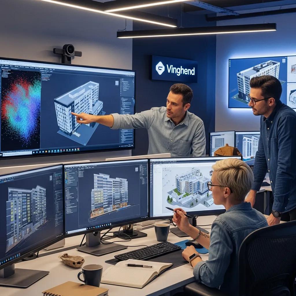
What Role Does BIM Modeling Play in Clash Detection and Coordination?
BIM modeling converts classified point cloud geometry into parametric elements for clash detection and interdisciplinary coordination. Using Navisworks for federated coordination and Revit for native modeling, modelers turn point-cloud segments into families and systems that respect construction tolerances and fabrication constraints. Coordinated models feed issue tracking, reduce RFIs, lower rework, and clarify construction sequencing. Regularly integrating scan-derived models into coordination cycles ensures as-built conditions inform clash resolution and sequencing throughout preconstruction.
How is Point Cloud to BIM Conversion Applied Across Different Industries?
Scan-to-BIM workflows adapt to industry-specific constraints and regulations, making the method valuable for commercial construction, healthcare, industrial plants, and historic preservation. Each sector prioritizes different deliverable attributes — healthcare demands tight tolerances and validation metadata, industrial sites require piping and equipment accuracy for shutdown planning, and historic preservation needs high-resolution capture for façade and material records. Tailoring scan density, LOD, and QA criteria to each industry ensures the resulting model supports immediate construction tasks and long-term facility needs.
Typical industry use cases include:
- Commercial Construction: Fast coordination across structural, architectural, and MEP trades to shorten preconstruction cycles.
- Industrial/Manufacturing: Accurate equipment and piping models for retrofit planning and fabrication verification.
- Healthcare & Pharmaceutical: Tight MEP coordination and validation for compliance-sensitive systems and minimal downtime.
- Historic Preservation: High-resolution documentation of existing conditions for conservation planning and reversible interventions.
These examples show how adapting scan density, LOD, and metadata to the sector produces models that hand off cleanly between design and operations teams.
What are the Benefits of Scan to BIM for Healthcare and Pharmaceutical Facilities?
In healthcare and pharmaceutical projects, scan to BIM supports strict tolerances, validated MEP routing, and reduced downtime during retrofits or equipment changes. High-accuracy as-built models verify anchor points, clearances, and equipment locations — cutting site rework and supporting compliance records. Coordinated models act as a single source of truth for qualification activities, helping contractors, engineers, and facilities teams align on sequencing and isolation procedures. That precision lowers the risk of schedule slips in environments where disruptions carry high operational and regulatory costs.
How Does Scan to BIM Support Historic Preservation and Renovation Projects?
For historic preservation, scan to BIM records detailed geometry and surface information that preserves architectural character and material context for conservation planning. High-resolution point clouds capture textures, moldings, and irregular surfaces that traditional surveys can miss; models can include material metadata to guide restoration methods. Accurate baselines let designers test retrofit options without risking irreversible changes to historic fabric and support decisions that balance conservation goals with modern performance upgrades.
What Challenges Exist in Point Cloud to BIM Conversion and How Does CCLS Address Them?
Point cloud to BIM conversion brings technical challenges — noise and occlusions, large dataset management, LOD mismatches, and coordinate inconsistencies — that can affect model accuracy if not addressed. Mitigation requires strict QA at capture and registration, automated classification to handle volume, clear LOD agreements in scoping, and interoperability testing before handoff. Identifying these risks early and specifying controls reduces surprises and aligns outputs with fabrication and construction needs.
Common problems and practical solutions include:
- Noise and occlusions: Targeted scan coverage and filtering strategies preserve needed geometry while removing spurious points.
- Large file handling: Dataset decimation, tiling, and cloud processing keep workflows responsive during modeling.
- LOD mismatch: Define LOD in the contract with clear acceptance criteria and sample deliverables.
- Coordinate mismatch: Establish control and verify with survey-grade instruments before modeling begins.
The table below links each challenge to verification techniques and the expected outcome.
| Problem | Mitigation / Verification | Outcome |
|---|---|---|
| Noise & occlusions | Adaptive filtering, manual QA | Cleaner dataset enabling accurate modeling |
| Large datasets | Tiling, cloud processing | Faster modeling workflows and reduced crashes |
| LOD mismatch | Contracted LOD matrix | Clear expectations and acceptance criteria |
| Coordinate issues | Survey control, total station checks | Model aligns with construction coordinates |
CCLS mitigates these risks with workflow rigor and careful tool selection, combining automated classification with manual verification so final models meet project tolerances and reduce coordination cycles.
How is Noise and Data Quality Managed During Point Cloud Processing?
We manage noise and data quality with a mix of automated filters and targeted manual review so critical geometry stays intact while spurious returns are removed. Common methods include statistical outlier removal and surface-based smoothing, but human review is essential in congested MEP zones where geometry is complex. Processed clouds are checked against survey control points to quantify residuals; acceptable tolerances are defined in the project’s LOD and deliverable standards. This blend of automation and spot checks balances speed and fidelity for reliable modeling results.
How Does CCLS Ensure Seamless Integration with BIM Software Platforms?
We ensure interoperability by delivering files and structures compatible with common platforms — linked point clouds in Revit, federated models for Navisworks, and cleaned point cloud extracts for ReCap or Cyclone. Handoff packages include modeled elements, federated clash reports, and point cloud extracts with metadata so teams can use the models immediately. Interoperability testing — opening deliverables in client environments to validate families, coordinates, and schedules — is a standard QA step to minimize friction during coordination.
Why Choose CCLS for Your Seamless Point Cloud to BIM Model Conversion Needs?
CCLS stands apart through precision-focused capture, practical BIM modeling, and hands-on VDC consulting that together reduce rework and speed coordination. We rely on survey-grade instruments (including Trimble Robotic Total Stations), experienced technicians, and modeling specialists who translate point clouds into construction-grade BIM deliverables. Our family-owned structure and direct oversight mean closer collaboration and faster field verification when projects need it. If you require both survey accuracy and coordination-ready models, we offer consultations to align deliverables with construction tolerances and schedule priorities.
Key differentiators include:
- Precision Tools: Survey-grade equipment and robotic total stations to tie scans to construction coordinates.
- Technical Modeling: Revit-based workflows focused on agreed LOD and fabrication readiness.
- Integration Focus: VDC consulting that connects scan deliverables with field layout and sequencing.
Together these strengths deliver fewer onsite conflicts, cleaner handoffs, and models that slot into your existing BIM process. For example, a recent coordination project used precise scan capture and alignment to reduce onsite rework during a complex MEP retrofit. If you’re ready to turn reality capture into dependable BIM assets, submit a project or schedule a consultation so we can confirm scope and tolerances.
What Expertise and Technologies Differentiate CCLS in Scan to BIM Services?
CCLS combines experienced technicians, BIM modelers, and VDC consultants using an integrated technology stack to produce accurate, coordinated deliverables. Core capture tools include terrestrial laser scanners and LiDAR, with Trimble Robotic Total Stations for control. Our software stack commonly includes Revit, Navisworks, ReCap, and point-cloud processing suites for registration and modeling. That mix supports workflows that prioritize coordinate fidelity, classification accuracy, and model interoperability. Our process rigor — from control setup to registration verification and model validation — produces reliable outputs aligned with construction and fabrication workflows.
How Do Case Studies Demonstrate CCLS’s Success in Point Cloud to BIM Projects?
Our case summaries follow a simple pattern: define the challenge, apply a targeted scan-to-BIM approach, and measure outcomes against rework and coordination metrics. Case bullets typically note project context, scan and modeling approach, and measurable results such as reduced clash resolution time or avoided rework. These concise examples show how precise capture and disciplined modeling deliver construction value and help projects stay on schedule. When evaluating providers, look for case evidence that matches your scope — MEP-heavy retrofits, healthcare validation, or historic conservation — to confirm relevant experience and fit.
Frequently Asked Questions
What types of projects benefit most from Point Cloud to BIM conversion?
Point Cloud to BIM conversion is especially valuable for commercial construction, healthcare facilities, industrial plants, and historic preservation projects. Each sector has distinct needs — healthcare prioritizes tight MEP tolerances, industrial sites demand equipment and piping accuracy, and preservation projects need high-resolution detail capture. Tailoring LOD and metadata to those needs ensures models support both immediate construction tasks and long-term facility management.
How can I ensure the quality of the Point Cloud data before conversion?
Start with a solid data-acquisition plan: set control points, use high-accuracy scanning equipment, and schedule QA checks during capture and registration. Automated filtering helps process volume, but manual reviews catch complex geometry issues. These steps ensure the point cloud is clean and ready for effective modeling in BIM software.
What are the common software tools used in the Point Cloud to BIM process?
Common tools include Autodesk Revit for modeling, Navisworks for clash detection and federated coordination, and ReCap for point cloud processing. Other platforms such as Cyclone and classification suites assist with registration and cleanup. Together, these tools convert raw point cloud data into structured BIM models that meet project requirements.
What is the typical timeline for a Point Cloud to BIM project?
Timelines vary with project size, complexity, and data quality. Small projects can complete in a few weeks; larger, complex jobs may take several months. Factors that affect schedule include point cloud density, number of scans, and QA/QC rigor. Clear milestones and agreed deliverable expectations at the outset help keep the workflow on track.
How does CCLS handle data interoperability with existing BIM systems?
We deliver files in formats compatible with major BIM platforms like Revit and Navisworks, including linked point clouds and federated models for coordination. Interoperability testing — opening deliverables in client environments to validate families, coordinates, and schedules — is part of our QA routine to ensure smooth integration into existing workflows.
What are the cost implications of Point Cloud to BIM conversion?
Costs depend on project size, complexity, and required detail. While upfront investment in scanning and modeling can be significant, the downstream savings from reduced rework, faster coordination, and more accurate fabrication often offset those costs. High-quality scanning and modeling are an investment in predictable project outcomes and lifecycle value.
Conclusion
Converting point clouds to BIM provides clear benefits: better accuracy, faster coordination, and cost savings across the construction lifecycle. Done right, it improves project outcomes and supports long-term facility management and renovation planning. If you want to leverage these advantages, talk with us about how CCLS can tailor a scan-to-BIM approach to your project and deliver dependable, construction-ready models.