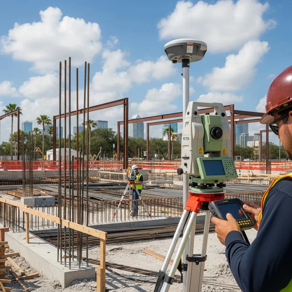
Structural Layout with a Robotic Total Station in Tampa, FL — Precision Construction Solutions by CCLS
Using a Robotic Total Station (RTS) for structural layout lets a single operator place model coordinates on the ground with millimeter-level accuracy. That precision aligns foundations, anchor bolts, structural steel, and MEP hangers to BIM locations so assemblies fit as designed — cutting rework and schedule risk. Tampa projects add local variables such as sandy soils, high humidity, and compressed weather windows, so dependable control and verification are essential. RTS workflows combine accurate instruments, a robust control network, and digital verification to address those challenges. This article explains why RTS is the right choice for Tampa structural work, outlines core RTS services for foundations and MEP, shows how BIM and VDC integrate with field stakeout, and offers practical anchor-bolt and foundation procedures, example deliverables, and guidance for engaging Conway Coordination and Layout Services (CCLS) on Southeastern projects.
Why choose Robotic Total Station layout for structural projects in Tampa?
Robotic Total Station layout automates stakeout by combining electronic distance measurement and motorized tracking so a single operator can place points directly from the model. That workflow removes common human-transfer errors and delivers the tight tolerances needed to keep foundations and structural elements on line. On Tampa jobs — where schedules are tight, soils can settle, and multiple trades must coordinate — RTS reduces rework, shortens installation sequences, and improves safety by cutting repetitive manual measurements and limiting ground disturbance. Compared with manual methods or two-person total station setups, RTS delivers repeatable results faster and with fewer personnel, boosting productivity and lowering labor costs on time-sensitive projects.
In practice, RTS also speeds mobilization, provides consistent verification, and improves BIM-to-field interoperability to avoid clashes. The next section summarizes the technical advantages of RTS versus traditional layout methods.
What advantages does Robotic Total Station technology offer over traditional methods?
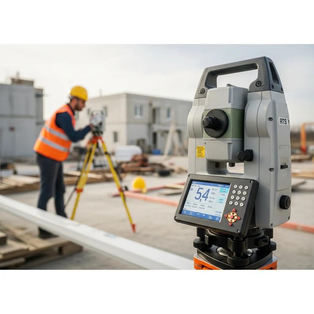
Robotic Total Stations bring automation, single-operator efficiency, and integrated field software that accelerate stakeout and verification compared with manual layout. Because the instrument uses model coordinates for direct stakeout, operator-to-operator variability drops and placement errors for anchor bolts and hangers decline. When paired with Trimble field tools, RTS lets teams quickly re-establish control, repeat stakeout points, and make on-the-fly coordinate updates — reducing crew hours on site and speeding turnover between trades. These gains help contractors meet compressed timelines without sacrificing dimensional control.
To see how precision translates to fewer mistakes, the next section looks at concrete examples of error reduction and rework avoidance.
How does precision layout reduce errors and rework in Tampa construction?
Precision layout reduces errors by getting installations right the first time, preventing common issues such as misplaced anchor bolts or offset MEP hangers that trigger corrective work. RTS cuts out manual coordinate conversions and transcription steps where human error often occurs, and verification scans confirm placements before pours or equipment installs. For example, fixing a misplaced anchor bolt after concrete cures can cost a full day of labor plus specialty remediation; avoiding that single mistake protects both schedule and budget. Routine pre-install checks and as-built snapshots improve downstream trade coordination and reduce lifecycle cost impacts.
Comprehensive structural layout services using Robotic Total Stations in Tampa
RTS workflows support a wide range of structural layout services: foundation and anchor bolt layout, structural steel alignment, MEP hanger placement, overhead systems, and as-built capture with 3D scanning. Each task follows a consistent workflow: model import, coordinate system alignment, control setup, stakeout, and verification documentation with task-specific tolerances and deliverables. Typical outputs include stakeout reports, verified coordinate tables, annotated as-built photos, and reconciliation logs that demonstrate tolerance compliance.
Below is a concise comparison of common RTS service applications and their typical attributes to help contractors set expectations.
| Service Application | Typical Accuracy | Primary Deliverable |
|---|---|---|
| Foundation & Anchor Bolt Layout | Millimeter to centimeter tolerance | Anchor coordinate verification report |
| MEP Hanger & Penetration Layout | ±5–15 mm depending on assembly | Hanger and penetration stakeout sheet |
| Overhead Hanger & Structural Steel Layout | Millimeter alignment for critical connections | Structural control and as-built snapshots |
| 3D Scanning / As-Built Documentation | Sub-centimeter capture | Registered point cloud and annotated QA report |
This table shows how each RTS application maps to contractor needs and how deliverables support quality control and installability. A quick list of common services follows.
- Foundation and anchor bolt stakeout with verification steps to avoid embedded misplacement.
- MEP hanger, sleeve, and penetration layout coordinated with trade installations.
- Structural steel layout for column and connection alignment.
- 3D scanning for accurate as-built capture and model reconciliation.
These service descriptions set the stage for a step-by-step look at foundation and anchor bolt workflows.
Conway Coordination and Layout Services (CCLS) delivers these workflows with Trimble Robotic Total Station technology from a family-owned, client-focused practice that values precision, digital integration, and responsiveness across the Southeastern U.S. We translate BIM models to field coordinates, maintain rigorous control networks, and produce verification packages that support contractor QA/QC. Our Tampa experience ensures workflows account for local site conditions and scheduling constraints. The section below walks through our foundation and anchor bolt process.
How does CCLS perform foundation and anchor bolt layouts with precision?
CCLS starts by importing the approved BIM or structural model and confirming the project coordinate system for direct model-to-field transfer. We establish a stable control network tied to project benchmarks and run redundancy checks to detect settlement or control drift — a common concern in sandy soils. Stakeout is performed with a Trimble Robotic Total Station that automates point placement while the crew verifies each anchor location and logs tolerances in verification reports. Finally, we deliver as-built photos and measurement logs for owner acceptance so contractors can proceed with confidence and minimize remediation risk.
The steps above describe our control and documentation sequence; the next section covers RTS support for MEP and overhead systems.
What are the key features of MEP and overhead layout services in Tampa?
RTS layout for MEP and overhead systems centers on precise hanger locations, sleeve and penetration placement, and multi-discipline routing coordination to ensure installability. The process begins with a clash-checked BIM export where hanger points and sleeves are tagged for stakeout; Trimble field tools translate those coordinates into control-ready points. On site, RTS ensures repeatable hanger placement and enables quick rework of misaligned points before assemblies go up, reducing lift time and trade interference. Deliverables typically include stakeout sheets, hanger verification, and coordinated as-built notes that feed back into the VDC model for downstream trades.
Integrating BIM and VDC with Robotic Total Station layout for Tampa projects

BIM and VDC integration means preparing coordination data so RTS instruments can stake points directly from the model, minimizing translation errors between design and construction. The key steps are aligning model coordinate systems, exporting verified stakeout points in compatible formats, and resolving clashes before field layout so crews only stake approved locations. This digital-first approach shortens the gap between model finalization and physical installation and reduces surprises from mismatched reference frames or unresolved design conflicts.
Common file formats and tools in BIM-to-field workflows include Revit exports, Navisworks federated views, and Trimble field software that accepts coordinate lists and point imports. Typical interoperability elements are:
- Revit coordinate exports for geometry and element locations.
- Navisworks clash reports and federated views for trade coordination.
- Trimble field software for point import and real-time stakeout.
These tools form the bridge between virtual coordination and accurate field execution; the next section explains how BIM coordination improves layout outcomes.
How does BIM coordination enhance field layout accuracy?
BIM coordination improves layout accuracy by resolving clashes, clarifying design intent, and providing verified coordinates that RTS instruments can stake directly. The workflow includes model validation, clash detection, and export of approved point sets that preserve the project coordinate system and elevation datum. By removing ambiguous dimensions and supplying precise coordinates for hangers, sleeves, and anchors, BIM reduces field interpretation, leading to fewer RFIs, less on-site rework, and smoother sequencing between structural and MEP trades.
Having a VDC plan in place also helps by sequencing work and flagging readiness issues before mobilization, which we cover next.
What role does VDC play in streamlining Tampa construction layouts?
VDC complements RTS layout by providing sequencing, coordination deliverables, and readiness checks that confirm which areas are cleared for stakeout and which need resolution. The VDC team compiles clash reports, prepares installability packages, and schedules layout windows so field crews work efficiently with minimal downtime. Integrating VDC outputs with robotic stakeout reduces mobilization interruptions and ensures measurements occur under controlled conditions, shortening schedules and lowering cumulative risk on complex Tampa projects.
Addressing Tampa’s unique construction challenges with Robotic Total Station precision
Tampa’s coastal geology and climate create specific layout risks: sandy soils that allow control settlement, high humidity that affects instrument optics, and a storm season that compresses verification windows. The primary issue is preserving a stable control network and reliable stakeout windows so coordinates stay accurate from initial layout through installation. RTS workflows mitigate these risks with redundant control points, staged verification before critical pours or lifts, and weather-aware scheduling that prioritizes verification during stable conditions.
The table below links common Tampa site challenges to accuracy risks and practical mitigation strategies that increase layout resilience.
| Site Challenge | Accuracy Risk | Mitigation Strategy |
|---|---|---|
| Sandy soils / settlement | Control point movement | Control densification and short-interval verification |
| High humidity / thermal refraction | Measurement variance | Use short sight distances and instrument calibration |
| Storm season / compressed scheduling | Limited verification windows | Weather-aware mobilization and staged verification |
| High water table / dewatering | Foundation elevation drift | Tie control to stable benchmarks and monitor settlement |
This mapping shows how targeted mitigations preserve measurement integrity and cut layout-related rework on Tampa projects. The following sections explain soil and weather impacts and practical solutions in more detail.
How do soil and weather conditions affect structural layout accuracy in Tampa?
Soil and weather affect layout accuracy by undermining control stability and altering measurement physics like refraction and optics. In sandy soils, control points can shift as fills consolidate or loads change, so control networks should be densified and checked frequently. Humidity and temperature gradients can change apparent line-of-sight during long shots, which calls for shorter sight distances or environmental correction protocols. Monitoring control points with staged verification and re-checking critical coordinates before permanent installations reduces the risk of latent errors.
The next subsection describes practical mitigation techniques experienced layout providers use in the field.
What solutions does CCLS provide to overcome Tampa-specific layout issues?
CCLS uses a layered mitigation strategy on Tampa projects: denser control networks, staged verification at critical phases, and complementary 3D scanning to confirm as-built conditions. We emphasize redundancy — multiple control points and repeated checks — to detect settlement early and correct it before permanent work proceeds. We also schedule layout windows to avoid peak thermal gradients and known storm periods, and we use registered point clouds for post-installation reconciliation where environmental variability may have affected initial measurements. This combination of control rigor, documentation, and weather-aware planning minimizes thermal/refraction impacts and soil-related movement on sensitive projects.
These tactics help contractors avoid costly rework; next we share real outcomes and case summaries that show measurable benefits.
Case studies and proven results of Robotic Total Station layout in Tampa, FL
Project results show RTS workflows reducing rework and compressing schedules by resolving coordination issues before field installation. Common problems — mislocated anchor bolts, delayed hanger installs, and sequencing conflicts between structural and MEP trades — are addressed with precise stakeout, verification reporting, and model reconciliation. Below are brief anonymized case summaries in a problem → RTS solution → measurable benefit format to illustrate expected returns.
- Foundation alignment for a mid-rise commercial building: Problem — anchor bolt offsets risking column misalignment; Solution — RTS model transfer with redundant verification; Benefit — avoided anchor correction, saving days of remedial work and protecting the schedule.
- Hospital mechanical rack installation: Problem — potential clashes between racks and ceiling systems; Solution — VDC-driven clash resolution and RTS stakeout of revised hanger locations; Benefit — installation completed without rework and improved trade sequencing.
- Warehouse overhead system: Problem — long spans with cumulative alignment risk; Solution — RTS control network and sectional verification; Benefit — less shop rework and faster commissioning of overhead systems.
These examples highlight sectors we commonly serve — healthcare, industrial, and commercial — and demonstrate measurable outcomes contractors can expect. The next section ties these results to CCLS’s engagement process.
What are examples of successful foundation and structural layout projects in Tampa?
One foundation example involved resolving anchor tolerance issues before concrete placement by translating approved BIM coordinates into a verified stakeout and completing immediate pre-pour checks. The RTS approach avoided core drilling and re-setting, preserving schedule and budget. In structural steel work, model-linked field verification ensured column coordinates matched shop expectations and eliminated fit-up delays. These anonymized outcomes show how precise layout prevents issues that often surface only after assemblies arrive on site.
How has CCLS helped Tampa clients save costs and improve efficiency?
CCLS’s RTS-led coordination reduces repeated labor cycles and minimizes corrective work by ensuring installations meet modeled coordinates the first time. Typical benefits include avoided rework hours, less downtime while coordination is resolved, and fewer change orders tied to misaligned embeds or hangers. By delivering verification reports and registered as-built snapshots, we shorten acceptance cycles and enable quicker turnover to following trades. Contractors gain improved schedule predictability and lower overall costs from fewer disruptions and clearer documentation for owner acceptance.
Frequently Asked Questions
What types of projects benefit most from Robotic Total Station layout?
RTS layout is ideal for projects that require high precision and multi-trade coordination — commercial buildings, hospitals, industrial facilities, and any work with tight tolerances. Its automation and accuracy reduce alignment risk for anchor bolts, MEP systems, and overhead structures, helping installations fit as designed and stay on schedule.
How does weather impact the use of Robotic Total Stations in Tampa?
Tampa weather — high humidity and seasonal storms — can affect RTS performance. Humidity can cause thermal refraction that alters long-shot measurements, and storms limit verification windows. To manage this, we use weather-aware scheduling, shorter measurement cycles when needed, and frequent control checks so measurements remain reliable under changing conditions.
What training or qualifications do operators need for using Robotic Total Stations?
RTS operators need hands-on training in surveying methods, instrument operation, and field software. Familiarity with BIM and VDC is valuable since those systems feed stakeout points. Many operators hold surveying or geomatics certifications and gain accuracy through practical RTS experience and continuing education on new tools and workflows.
Can Robotic Total Stations be used for both indoor and outdoor projects?
Yes. RTS performs well outdoors for large-scale site layout and foundation work and indoors for MEP and overhead systems where accurate placement is critical. Environmental factors like lighting, line-of-sight, and interior reflections require adjustments to technique, but RTS remains a versatile tool for both conditions.
What are the cost implications of using Robotic Total Stations compared to traditional methods?
Although RTS has higher upfront equipment and expertise costs than traditional methods, the long-term economics often favor RTS. Reduced rework, faster turnover between trades, and fewer labor hours translate into schedule and budget savings that typically offset the initial investment — especially on complex projects.
How does CCLS ensure quality control during the layout process?
CCLS applies a strict quality-control regimen: we establish a stable control network, perform redundancy checks, and use verification scans before critical installations. Our deliverables—verification reports, annotated as-built photos, and measurement logs—document compliance with tolerances and support contractor and owner QA/QC.
What is the typical accuracy level achieved with Robotic Total Stations?
Robotic Total Stations typically deliver millimeter-to-sub-centimeter accuracy for stakeout tasks when backed by a well-established control network and proper procedures. Typical tolerances vary by task: anchor bolts and critical columns aim for millimeter-level placement, while general hanger locations commonly accept ±5–15 mm. Achievable accuracy depends on control quality, environmental factors (refraction, temperature), and model precision. Redundant control checks and 3D scanning help confirm that delivered accuracy meets contract tolerances.
How can Tampa contractors hire CCLS for precision layout services?
Contractors start by scheduling a project consultation where we review model files, scope, and schedule to prepare a scoped proposal. Helpful items to have ready include approved BIM files (Revit or federated model), critical tolerance requirements, and site benchmarks for control tie-in. After scoping, CCLS outlines mobilization steps, control setup, stakeout sequences, and deliverable formats, then schedules field mobilization to match trade sequencing. Clear model exports and prioritized coordination items speed quoting and mobilization.
Use this checklist to prepare for a CCLS engagement:
- Gather approved BIM/Revit files and note the coordinate system and elevation datum.
- Define critical tolerances for anchor bolts, columns, and hangers.
- Share site benchmark information or arrange access for control tie-in.
- Confirm preferred deliverables (stakeout sheets, verification reports, point clouds).
Conclusion
Robotic Total Station technology gives Tampa structural projects the precision they need to reduce errors, cut rework, and keep schedules on track. When paired with BIM and VDC coordination, RTS ensures field installations match design intent and accelerates handoffs between trades. Working with Conway Coordination and Layout Services (CCLS) means a practical, locally informed approach that accounts for Tampa’s site conditions and scheduling realities. Contact us to learn how our precision layout services can improve accuracy, reduce risk, and keep your next project moving.