Virtual Design & Construction Services in Charleston, SC: Practical, Complete Solutions to Streamline Your Project
Virtual Design and Construction (VDC) combines digital models, field capture, and coordinated workflows to cut rework and keep Charleston projects on schedule. This guide clarifies what VDC is, why it matters for local challenges—like historic renovations and congested MEP runs—and how tools such as BIM, 3D laser scanning, and robotic total stations deliver measurable time and cost savings. You’ll get a clear breakdown of core VDC services, how consulting and training shift contractor workflows, the technical elements of BIM coordination and scan-to-BIM, and why precise layout is critical for MEP and structural trades. Each section includes practical examples, technology overviews, comparison tables, and local use cases so owners, design teams, and contractors in Charleston can evaluate digital construction options with confidence and act on them right away.
What Are Virtual Design and Construction Services and Their Benefits in Charleston?
VDC is a coordinated process that links model-based design, construction sequencing, and field verification so design intent becomes a reliable basis for site work. It federates discipline models, runs clash detection, and ties model data to schedules and layout—producing clearer constructability reviews and fewer surprises in the field. The payoff is less on-site rework, faster procurement for prefabricated systems, and greater schedule certainty—advantages that matter in Charleston’s historic contexts and tight mechanical spaces. Knowing how each VDC service works helps teams prioritize consulting, BIM coordination, scan-to-BIM, or precision layout where they’ll deliver the greatest value.
Below is a straightforward mapping of core VDC components to outcome-focused benefits for quick comparison and decision-making.
VDC components and their direct benefits:
| Component | Primary Benefit | Example Outcome |
|---|---|---|
| VDC Consulting | Aligned workflows | Defined roles, LOD standards, fewer RFIs |
| BIM Modeling & Coordination | Fewer clashes | Federated models with resolved conflicts before installation |
| 3D Laser Scanning | Reliable as-built data | Point clouds for renovation verification |
| Robotic Total Station Layout | Precise field placement | Millimeter-level anchor bolt and hanger layout |
The table shows how targeted VDC services translate to measurable project improvements and helps teams decide where to invest to lower downstream risk. Next, we outline how VDC reduces time and cost through concrete, implementable mechanisms.
How Does VDC Improve Construction Project Efficiency and Cost Reduction?
VDC cuts waste and cost by resolving coordination issues in the model, enabling prefabrication, tightening sequencing, and minimizing field rework. Clash detection in federated models prevents on-site conflicts that generate RFIs and expensive fixes. Fabrication-ready models shift work from the field to controlled shop environments, shortening installation windows and reducing labor variability. Linking models to schedules and procurement improves sequencing and staging, decreasing downtime and moving critical-path activities faster.
- Clash detection: Finds spatial conflicts early so installations proceed smoothly.
- Prefabrication: Produces fabrication-ready models that reduce field labor and surprises.
- Schedule integration: Keeps model updates aligned with sequencing to limit delays.
- Reduced verification cycles: Uses scanned as-built data to validate installations quickly.
Combined, these practices shrink contingency needs and make project outcomes more predictable—setting the stage for the specific technologies that power VDC workflows in Charleston.
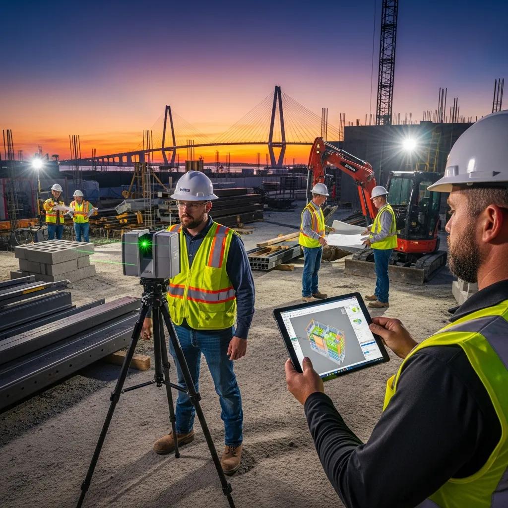
What Technologies Power VDC Services in Charleston, SC?
VDC depends on an integrated toolset—modeling, coordination, reality capture, and layout—that closes the loop between design and the field. Autodesk Revit and federated viewers bring discipline models together for clash checks and shop drawings. Navisworks (and similar tools) run clash rules, produce visual reports, and support coordination sessions with trades. 3D laser scanning and point-cloud processing capture accurate as-built conditions. Trimble Robotic Total Stations and related layout systems convert model coordinates into precise field positions for installation and verification.
- Autodesk Revit: Core for discipline modeling and managing LOD.
- Navisworks / Coordination Viewers: Federate models and run clash detection.
- 3D Laser Scanners / Point Cloud Tools: Capture reality data for model reconciliation.
- Trimble Robotic Total Station: Automates high-precision field layout.
Together these tools create a reliable pipeline—model → clash → prefabrication → layout—that lowers uncertainty from design through installation. The next section explains how targeted consulting helps organizations adopt this pipeline successfully.
How Does VDC Consulting Enhance Construction Workflows in Charleston?
VDC consulting combines assessment, implementation planning, and training to embed digital construction into existing workflows. A typical engagement starts with a workflow assessment that documents current BIM use, communication paths, and LOD expectations, then defines a roadmap for model deliverables, coordination cadence, and QA checkpoints. Implementation covers template setup, clash-management protocols, and integrations between modeling platforms and field layout tools. On-site coaching and training ensure trade partners and project leaders adopt the standards and data routines needed to sustain coordination gains.
Effective consulting pairs technical setup with change management: we clarify roles, create deliverable checklists, and provide hands-on training so models drive field actions rather than sit unused. For phased renovations or historic sites in Charleston, consulting identifies which deliverables—scan-to-BIM, LOD 300/400 shop models, or fabrication-ready outputs—are essential to reduce risk. Teams can request a consultation with Conway Coordination and Layout Services (CCLS), a family-owned firm specializing in VDC construction services and precision layout across the Southeast, to arrange a workflow assessment.
What Strategic Guidance and Training Are Offered in VDC Consulting Services?
Strategic guidance focuses on workflow mapping, defining Levels of Development (LOD), setting clash-management cadences, and training teams on Revit, Navisworks, and field-capture tools. Training can be on-site bootcamps for trades, remote workshops for project teams, or blended coaching tied to live coordination cycles. Consultants create role-based playbooks—what designers, subcontractors, and superintendents must deliver at each milestone—and checklists that align model LOD with procurement and fabrication needs. Training prioritizes practical data flows: how point-cloud scans feed model reconciliation and how layout coordinates are exported for field staking.
These organized training activities reduce handover confusion and make model-based verification routine, preparing teams to adopt scan-to-BIM and precision layout practices covered next.
How Does VDC Consulting Integrate BIM and 3D Scanning for Project Success?
Integrating BIM with 3D scanning starts by capturing accurate as-built conditions, processing point clouds, and reconciling scans with discipline models to confirm geometry and clearances. The pipeline follows scan → registration → point-cloud cleanup → model reconciliation → coordination, using scanned geometry to refine design models and produce clash-aware, fabrication-ready outputs. Consultants set tolerance standards, registration checkpoints, and deliverable formats (for example, indexed point clouds or RCPs) so model updates remain auditable and usable by trades. That validation against reality data reduces site surprises before fabrication and layout begin.
Using point clouds as a single source of truth lets teams plan prefabrication confidently and produce measured drawings for historic preservation or retrofit work. Next we outline the BIM deliverables and coordination features teams should specify.
What Are the Key Features of BIM Modeling and Coordination Services in Charleston?
BIM modeling and coordination produce federated models, clash reports, and fabrication-ready deliverables so design intent becomes buildable assemblies. Core features include systematic federation of architectural, structural, and MEP models; recurring coordination cycles with documented clash resolution; and shop drawings or LOD-specific outputs for prefabrication. Coordination services also verify model metadata, element sizing, and routing constraints so models serve reliably for fabrication and field layout. Together, these features reduce RFIs and create a clean handoff from design to shop fabrication and installation.
Below is a quick comparison of typical BIM outputs to help technical decision-makers specify deliverables clearly.
| Deliverable | Typical Level of Detail | Deliverable Format |
|---|---|---|
| Federated Model | LOD 300 | Navisworks/NWD, Revit links |
| Clash Report | N/A (coordination cycles) | CSV, PDF, model-marked views |
| Fabrication-Ready Model | LOD 350–400 | Revit, IFC, shop-drawing PDFs |
| As-Built BIM | LOD 300–350 from scans | Revit model derived from point cloud |
This quick reference clarifies expected detail and file formats so owners can write clear model requirements and deliverable schedules. Next we explain how clash cycles and model handoffs create fabrication-ready outputs.
How Does BIM Enable Clash Detection and Fabrication-Ready Models?
Clash detection starts with model federation, where discipline models are combined and rule sets flag interferences. Coordination cycles schedule resolution meetings, assign responsibility for each clash, and track verification until closure. To produce fabrication-ready models, teams move from LOD 300 design intent to LOD 350–400 by adding fabrication geometry, anchor points, and connection details required by shop fitters. Fabrication checklists commonly include modeled spools, hanger points, coordination notes, and exported cutting lists.
A standardized clash-resolution loop and a fabrication checklist shorten shop handoffs and cut back-and-forth during installation, preparing the project for precision layout and robotic staking in the field.
What Are the Benefits of BIM for MEP and Structural Coordination?
BIM delivers clear benefits for MEP and structural trades: fewer spatial conflicts, more accurate shop drawings, and the ability to prefabricate assemblies that speed installation. For MEP systems, coordinated routing minimizes on-site adjustments and preserves maintenance clearances. For structures, verified anchor bolt locations, embedded plates, and accurate penetrations align with architectural and MEP requirements. Overall, BIM reduces RFIs, shortens fabrication lead times, and improves first-pass installation accuracy for both trades.
These coordination gains lead naturally into how reality capture supports accurate construction by providing the as-built baseline needed for confident model reconciliation.
How Does 3D Laser Scanning Support Accurate Construction in Charleston?
3D laser scanning speeds site capture and delivers dense point clouds that represent existing conditions with geometric fidelity suitable for scan-to-BIM and verification. Scanners record spatial relationships quickly so teams can register scans, filter noise, and export usable point clouds for modelers. Typical deliverables include registered point clouds, orthophotos, control reports, and QA metrics that document scan accuracy and tie into project coordinate systems. For Charleston projects dealing with historic fabric or tight retrofit constraints, scan data reduces uncertainty and shortens verification cycles that otherwise consume field hours.
The table below outlines the capture-to-deliverable pipeline and the file outputs teams should expect from a scan engagement.
| Phase | Description | Typical Outputs |
|---|---|---|
| Capture | Field scanning and control | Raw point clouds (E57/PTS), control sheets |
| Registration | Align scans into one coordinate set | Registered point cloud files, error reports |
| Processing | Noise filtering and clipping | Cleaned point clouds, orthophotos |
| Modeling | Scan-to-BIM conversion | Revit as-built models, clash overlays |
Knowing these outputs helps teams set scan tolerances and deliverable requirements that match model LOD and layout needs. Next we cover the role of point-cloud processing.
What Is the Role of 3D Reality Capture and Point Cloud Processing?
Reality capture creates a precise geometric record of existing conditions that forms the basis for model reconciliation and retrofit design. Processing removes noise, registers multiple scans to a single coordinate system, and segments areas for modeling so modelers can trace or validate geometry. Common exchange formats include E57 or LAS for point clouds and indexed orthophotos for visual reference, accompanied by QA reports that document registration errors. This workflow supports accurate retrofit design and reduces the number of field verification trips during coordination.
Using point clouds as the authoritative reference reduces ambiguity at handoff and builds confidence when producing fabrication-ready models—enabling scan-to-BIM to provide clear benefits on renovation work.
How Does Scan-to-BIM Enhance As-Built Documentation and Renovation Projects?
Scan-to-BIM turns registered point clouds into as-built Revit models that reflect true field conditions, letting designers and contractors plan retrofits with higher accuracy. This cuts the number of on-site verification cycles and guides precise modifications to structural and MEP systems for historic preservation or tenant improvements. Scan-to-BIM also supports measured drawings and dimensional checks for tight-tolerance equipment retrofits, lowering the risk of late-stage changes. By specifying LOD expectations for as-built models, teams capture the right level of detail for design and prefabrication needs.
Accurate as-built BIM models shorten procurement and installation timelines and prepare projects for high-precision field layout with robotic total station technology.
Why Choose Robotic Total Station Layout for Precision Construction in Charleston?
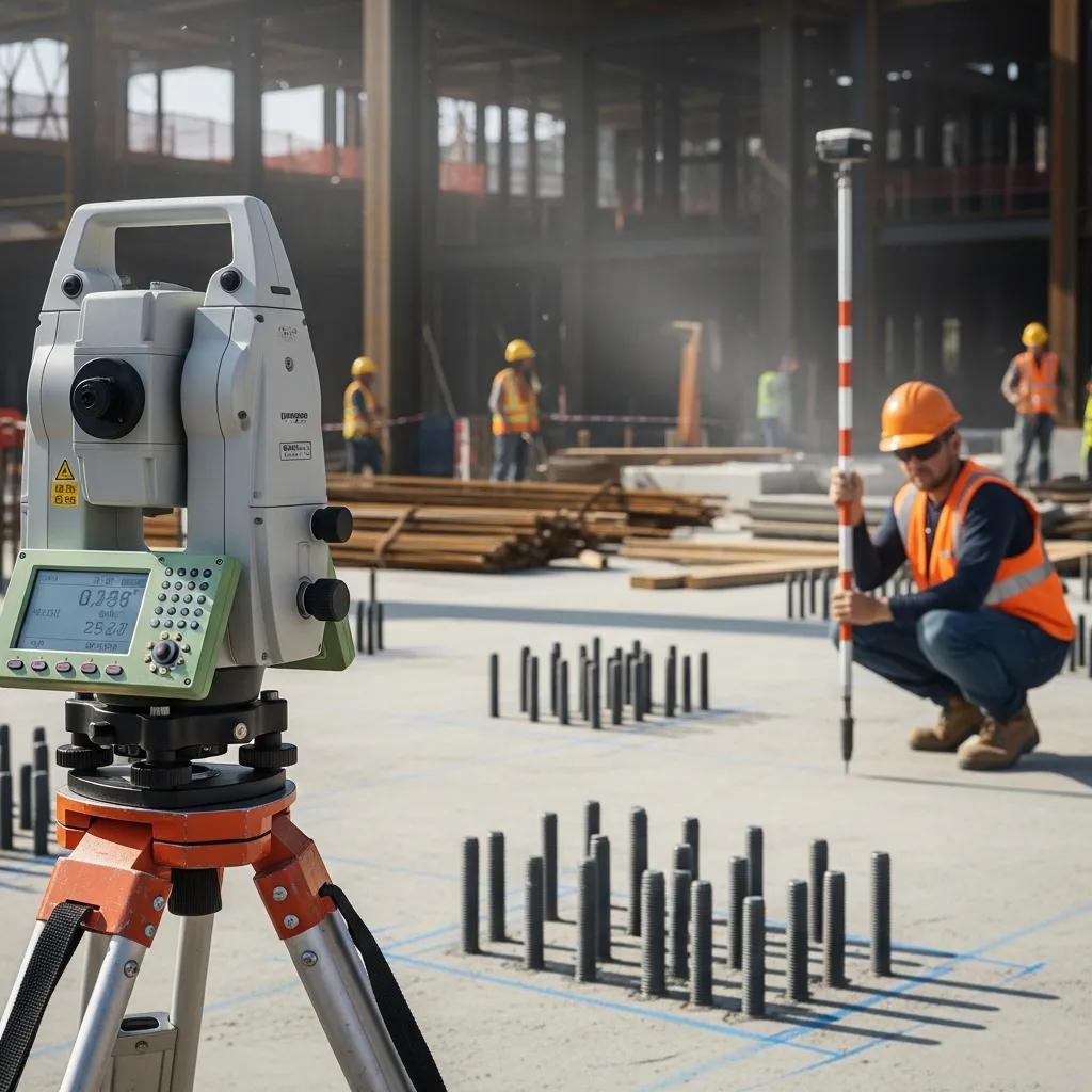
Robotic total station layout delivers repeatable, millimeter-level placement of anchors, hangers, and structural staking—accuracy traditional manual methods struggle to match. The system uses model coordinates and reflectorless measurement to position points in the field and can automate staking sequences for MEP hanger lines, anchor bolts, and structural piling. Compared with tape-and-plumb methods, robotic systems reduce human error, speed stakeout cycles, and produce verifiable QA records for as-built checks. On Charleston projects with tight clearances or critical equipment tolerances, precision layout materially reduces installation rework.
Conway Coordination and Layout Services (CCLS) uses Trimble Robotic Total Station solutions as part of its precision layout offerings, integrating model coordinates to deliver accurate field staking and anchor bolt verification. Contact CCLS to discuss project-specific layout plans and verification routines.
| Technology | Accuracy | Typical Use Case |
|---|---|---|
| Robotic Total Station | Millimeter-level | Anchor bolts, hanger layout, structural staking |
| Traditional Total Station | Sub-centimeter | Survey control and baseline layout |
| Conventional Layout (manual) | Centimeter+ | Preliminary stakes, simple layouts |
This comparison helps teams choose the right layout approach for each task. The sections that follow explain how accuracy is achieved and where robotic layout adds the most value.
How Does Robotic Total Station Technology Ensure Millimeter-Level Accuracy?
Robotic total stations reach high accuracy through precise angular measurements, EDM distance readings, and ties to survey control that anchor model coordinates to site control points. Regular calibration and field QA—resection checks, control tie-backs, and reference verification—keep measurements reliable across staking sequences. The robotic unit follows programmed staking lists exported from the model, reducing transcription errors and allowing quick re-staking when models change. QA typically includes photos and stake-check reports that document as-built placement against model tolerances.
Those QA practices produce traceable evidence of correct installation and feed directly into coordination cycles that validate fabrication-ready models before layout.
What Are the Applications of Robotic Layout in MEP, Structural, and Anchor Bolt Installations?
Robotic layout is ideal for MEP hanger lines, anchor bolt placement for equipment baseplates, and structural staking where tolerances matter. For MEP, robotic staking ensures hangers and supports match prefabricated assemblies, reducing fit-up issues. Anchor bolt verification prevents costly rework by confirming embedded items match shop drawings before pours or deliveries. Structural layout benefits from precise column lines and footing edges, improving downstream fit and reducing tolerance-related delays.
These field applications show how robotic layout turns model coordinates into dependable field geometry, which leads into the industries that benefit most from VDC adoption.
Which Industries Benefit Most from VDC Services in Charleston, SC?
In Charleston, healthcare, industrial/manufacturing, commercial fit-outs, and historic preservation projects see standout benefits from VDC: better coordination, less downtime, and accurate as-built records. Healthcare projects gain from tightly coordinated MEP and phased sequencing that minimize disruptions. Industrial and manufacturing sites use VDC for equipment-fit checks and process alignment before installation. Commercial fit-outs and preservation work rely on scan-to-BIM for accurate documentation while protecting original fabric and accelerating occupancy.
- Healthcare: Phased MEP coordination, equipment clearance checks, and infection-control sequencing.
- Industrial / Manufacturing: Equipment fit-checks, process layout validation, and reduced retrofit downtime.
- Commercial / Fit-Out: Prefabrication of modular systems and fast turnarounds for tenant occupancy.
- Historic Preservation: Scan-to-BIM for measured drawings and documentation of existing conditions.
These industry-specific advantages help stakeholders prioritize VDC services by project risk profile. Conway Coordination and Layout Services can provide tailored proposals and on-site assessments for owners and contractors who want sector-focused guidance.
How Does VDC Address Challenges in Healthcare and Industrial Construction?
In healthcare and industrial settings, VDC reduces regulatory and sequencing risk by enforcing model-based coordination and planning. For healthcare, modeling MEP and medical gas systems in coordination cycles prevents clashes that could cause shutdowns or rework in critical areas. In industrial environments, VDC verifies equipment foundations and utility routing against process needs, lowering the chance of expensive relocations. Combining scan-verified as-built data with fabrication-ready models shortens verification loops and speeds critical-path installations.
These workflows reduce operational risk and support tighter commissioning schedules, preparing teams to apply VDC to commercial and preservation projects as well.
What Are the Advantages of VDC for Commercial and Historic Preservation Projects?
Commercial fit-outs and historic preservation benefit from VDC’s accurate as-built documentation, coordinated retrofit planning, and selective prefabrication that minimizes site impact. Scan-to-BIM captures measured context for historic fabric so designers can plan sensitive interventions while delivering modern services. For commercial fit-outs, prefabricated assemblies and shop-ready models accelerate occupancy and limit tenant disruption. Together, these approaches reduce schedule uncertainty and protect fragile elements during renovations.
By combining scan-to-BIM, BIM coordination, and precision layout, teams achieve predictable outcomes where as-built accuracy and minimal disruption are priorities.
Frequently Asked Questions
What is the difference between VDC and traditional construction methods?
VDC shifts the focus from sequential, 2D-driven workflows to integrated, model-based collaboration. Instead of waiting to discover problems in the field, teams use 3D models for clash detection and sequencing, resolving issues before installation. That proactive approach reduces errors, cuts rework, and improves delivery times compared with traditional methods that rely heavily on paper drawings and reactive fixes.
How can VDC services be tailored for historic renovation projects?
For historic renovations, VDC uses scan-to-BIM to capture existing conditions accurately and produce as-built models that respect original architecture. Consulting then defines workflows and LOD expectations that prioritize preservation while allowing modern upgrades. Precise modeling and coordination reduce the risk of damaging existing fabric during renovation and shorten verification cycles.
What role does training play in the successful implementation of VDC?
Training is essential. Structured programs teach teams how to use Revit, Navisworks, and reality-capture tools, and how to apply clash-detection and coordination best practices. Practical, role-based training builds confidence across designers, subcontractors, and superintendents so model data becomes an actionable part of construction rather than an isolated deliverable.
How does VDC impact project timelines in construction?
VDC shortens timelines by resolving coordination issues early, enabling prefabrication, and improving sequencing. By reducing on-site rework and speeding shop production, projects gain predictability and often complete critical-path activities sooner than with traditional workflows.
What are the common challenges faced when adopting VDC?
Common obstacles include resistance to change, upfront investment in tools and training, and integrating multiple software systems. Data management and stakeholder alignment also require attention. Successful adoption focuses on phased rollouts, clear communication, and targeted training to build momentum and measurable wins.
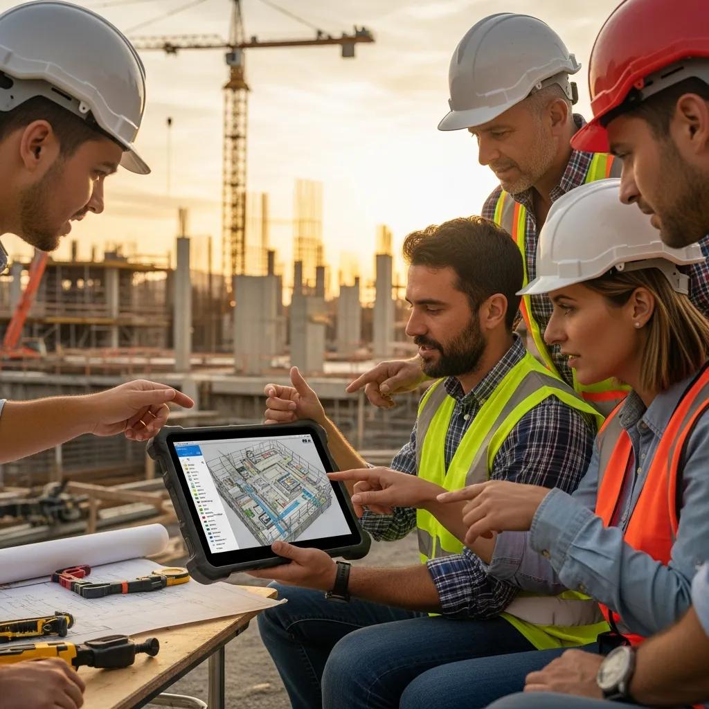
How does VDC enhance collaboration among project stakeholders?
VDC creates a shared platform—3D models and coordinated data—where architects, engineers, contractors, and owners can review progress, identify issues early, and make informed decisions. Regular coordination sessions and clash-resolution meetings keep everyone aligned, improving outcomes and reducing surprises.
Conclusion
Adopting VDC services in Charleston improves efficiency, reduces costs, and tightens coordination across diverse project types. By leveraging BIM, 3D laser scanning, and precision layout, teams can deliver precise, predictable results that respect both modern construction needs and historic preservation requirements. Working with experienced consultants ensures solutions are tailored to your project’s risks and goals. Contact our team to discuss a personalized VDC plan and see how digital construction can simplify your next Charleston project.