Critical Worker Safety Training Programs for Construction: Enhancing Site Safety with VDC, BIM, and Precision Technologies
Construction safety training increasingly relies on digital coordination rather than only classroom drills; Virtual Design and Construction (VDC), Building Information Modeling (BIM), and precision layout technologies provide actionable insights that reduce exposure, prevent errors, and improve on-site decision making. This article explains how these technologies function as practical extensions of worker safety training by enabling hazard simulation, clash detection, and highly accurate layout verification that collectively lower incident risk. Readers will learn how VDC and BIM map to formal risk management processes, the safety advantages of robotic total station and 3D scanning workflows, and how to combine digital tools with training programs for measurable results. The guidance is designed for safety managers, project coordinators, and construction firms seeking to align training curricula with model-driven site planning and verification. We cover VDC applications, BIM risk management, precision layout benefits, digital solutions for hazard prevention, case vignettes illustrating outcomes, and practical integration steps to operationalize model findings in toolbox talks and safety briefings.
Indeed, advanced technologies are increasingly recognized for their potential to significantly enhance the quality and effectiveness of safety training content in the construction industry.
Advanced Technologies for Construction Safety Training
Purpose – On-the-job training in the construction industry is an issue that requires increased efforts in order to improve safe working conditions. Nowadays, new advanced technologies are applicable to improve the quality of training contents. Site Training Tool developed by the authors stands as a pioneer of a new training methodology geared towards the development of current safety management practices.
Site training tool: a gamification-oriented approach in VDC industry, 2022
How Does Virtual Design and Construction Improve Construction Safety?
Virtual Design and Construction (VDC) is a coordinated, multidiscipline process that uses schedule-linked models, simulations, and visualizations to identify hazards before crews mobilize. By simulating construction sequences and site logistics in a virtual environment, VDC reduces worker exposure to dangerous conditions and allows teams to test mitigation strategies without putting people at risk. The mechanism is simple: transform design and schedule data into dynamic scenarios that reveal congestion, egress limitations, and interaction points between crews and equipment, then translate those findings into controls and procedures. The outcome is fewer on-site improvisations, clearer work sequencing, and better-informed safety briefings that directly lower incident probability.
This comprehensive approach to VDC is crucial for streamlining project management and enhancing overall construction accuracy.
VDC & BIM: Enhancing Construction Accuracy & Reducing Errors
VDC is a cutting-edge approach that integrates digital technologies, 3D modeling, and real-time collaboration to streamline project management and coordination. By creating a digital twin of the physical project, VDC allows stakeholders to visualize, analyze, and optimize every aspect of the construction process from conception to completion. This method significantly enhances design and construction accuracy, reduces costly errors, minimizes rework, and accelerates project timelines.
Revolutionizing Construction: The Synergy of VDC/BIM, Laser Scanning and Dusty Robotics, 2024
VDC delivers several practical mechanisms for safety improvement:
- Hazard simulation shows conflict points and unsafe access before ground is broken.
- 4D sequencing aligns tasks to reduce simultaneous exposures and congested zones.
- Site logistics modeling optimizes routing for materials and equipment to prevent pedestrian-equipment conflicts.
These capabilities inform toolbox talks and pre-task briefings, and the next section details the primary VDC construction services used to simulate hazards and optimize site logistics.
What Are the Key VDC Applications for Hazard Simulation and Site Logistics?
Key VDC applications include 4D sequencing, equipment and material flow simulation, and immersive visual walkthroughs that identify falls, trips, and collision risks prior to field work. 4D sequencing overlays schedule data on the model to show when work zones will overlap, allowing safety teams to stage tasks to minimize concurrent exposures. Material and equipment flow simulation reduces congestion by testing delivery windows and crane positioning, which lowers the chance of unexpected interactions between trades. Virtual crew walkthroughs and annotated model views serve as focused training inputs that make toolbox talks more concrete and actionable.
Different VDC outputs translate into specific safety actions:
- Use sequence-based visualizations to set exclusion zones and times.
- Produce annotated walkthroughs for crew-level briefings and permit boards.
- Test alternative routing and laydown areas virtually to prevent unsafe onsite rerouting.
These modeled scenarios feed directly into risk registers and control measures, which is the subject of the following subsection.
| VDC Application | Primary Function | Safety Benefit |
|---|---|---|
| 4D Sequencing | Schedule-model integration | Identifies concurrent work exposures and optimizes timing |
| Equipment Flow Simulation | Simulates crane and vehicle movements | Reduces pedestrian-equipment conflicts and congestion |
| Virtual Walkthroughs | Immersive crew visualization | Reveals fall/trip hazards and access issues before mobilization |
This comparison shows how targeted VDC applications convert modeling effort into concrete safety controls that can be relayed to crews and safety managers.
How Does VDC Facilitate Proactive Risk Assessment and Accident Prevention?
VDC facilitates proactive risk assessment by producing evidence-based model outputs that populate risk registers and drive mitigation planning rather than relying on anecdotal field observations. The process begins with model-based identification of likely incident scenarios, followed by quantitative evaluation of exposure duration and frequency; teams then test mitigation strategies in the virtual environment to verify effectiveness before field implementation. This model-to-register workflow enables safety managers to prioritize high-risk sequences and to design controls that are validated through simulation rather than trial-and-error. The result is fewer surprise hazards, more predictable work zones, and documented rationale for controls that inspectors and stakeholders can review.
When simulations suggest a residual risk, those findings are translated into specific actions such as revised access routes, temporary barriers, or modified sequencing, ensuring that prevention is built into the plan rather than applied reactively. The next major topic explains how Building Information Modeling complements VDC by centralizing information for risk management and regulatory compliance.
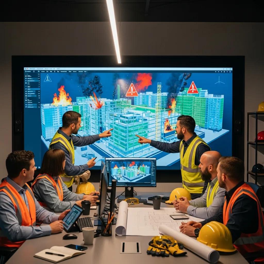
In What Ways Does Building Information Modeling Support Construction Risk Management?
Building Information Modeling (BIM) centralizes geometric, schedule, and systems data into an authoritative model that safety teams can query to detect clashes, coordinate trades, and document compliance controls. BIM reduces site risk by enabling automated clash detection runs, coordinated design reviews, and the creation of safety-specific model views that clarify field conditions for crews and inspectors. The mechanism is integration: when BIM aggregates MEP, structural, and architectural data, it becomes possible to surface conflicts that would otherwise require field fixes, thereby preventing unsafe rework and rushed improvisation. This centralized documentation also provides an auditable trace for compliance and post-incident analysis.
The transformative capabilities of BIM extend across the entire project lifecycle, offering robust support for comprehensive risk management.
BIM for Comprehensive Construction Risk Management
Building Information Modelling (BIM) offers capabilities that can transform risk management across the project lifecycle. The findings indicate BIM enables automated and visualization-based risk identification across project stages. BIM supports detailed qualitative and quantitative risk analysis through model simulations and integration with key performance data. It facilitates scenario-based evaluation of risk response plans through impact analysis. BIM also enables real-time risk monitoring by connecting models to construction progress data and early warning systems.
BIM and risk management: A review of strategies for identifying, analysing and mitigating project risks, M Numan, 2024
BIM contributes to risk management through three primary workflows:
- Automated clash detection to prevent structural and MEP conflicts.
- Coordination meetings backed by model visualizations that align trades.
- Model-driven documentation for permits, method statements, and safety plans.
These workflows help ensure that design-level issues are resolved prior to installation, minimizing hazardous corrections in the field and supporting safer construction execution.
How Does BIM Enable Clash Detection to Prevent Structural Conflicts?
Clash detection in BIM is a systematic process: import discipline models, run clash checks across systems, classify clashes (hard, soft, clearance), and route items for resolution through coordinated workflows. Hard clashes indicate physical interference requiring redesign, soft clashes flag potential spatial conflicts that may be resolved by coordination, and clearance checks ensure regulatory minimums for access and serviceability. Resolving these clashes at the model stage prevents scenarios where trades must perform risky in-field corrections, such as cutting structural members or working in congested spaces without proper controls. The workflow reduces rework, preserves schedule, and minimizes exposures caused by late-stage installation conflicts.
A simple clash type versus safety risk overview helps teams prioritize fixes:
| Clash Type | Typical Cause | On-site Safety Risk |
|---|---|---|
| Hard Clash | Overlapping geometry | Immediate obstruction, unsafe installation |
| Soft Clash | Spatial interference | Congestion, restricted egress |
| Clearance Issue | Insufficient service space | Unsafe maintenance and emergency access |
Understanding clash categories enables focused mitigation planning and reduces hazardous improvisation during installations.
What Role Does BIM Play in Supporting OSHA Compliance and Safety Protocols?
BIM supports OSHA compliance and safety protocols by producing model-driven documentation that aligns design intent with permit conditions, method statements, and inspection-ready views for safety officers. Safety-specific model views allow inspectors to verify clearances, fall-protection anchorage locations, and required egress without relying solely on field measurements. BIM also expedites change control by capturing approved revisions in the model and propagating those changes to downstream documentation, reducing the risk that crews will adopt unsafe workarounds in response to late changes. This traceability strengthens audit readiness and provides evidence for compliance reviews.
Using BIM to generate safety packs for permits or site inspections reduces ambiguity about who made design changes and why, creating a clearer link between design coordination and field safety practices. The next section examines how precision layout ties model accuracy to real-world safety through precise placement and verification.
How Does Precision Layout Technology Enhance Construction Site Safety?
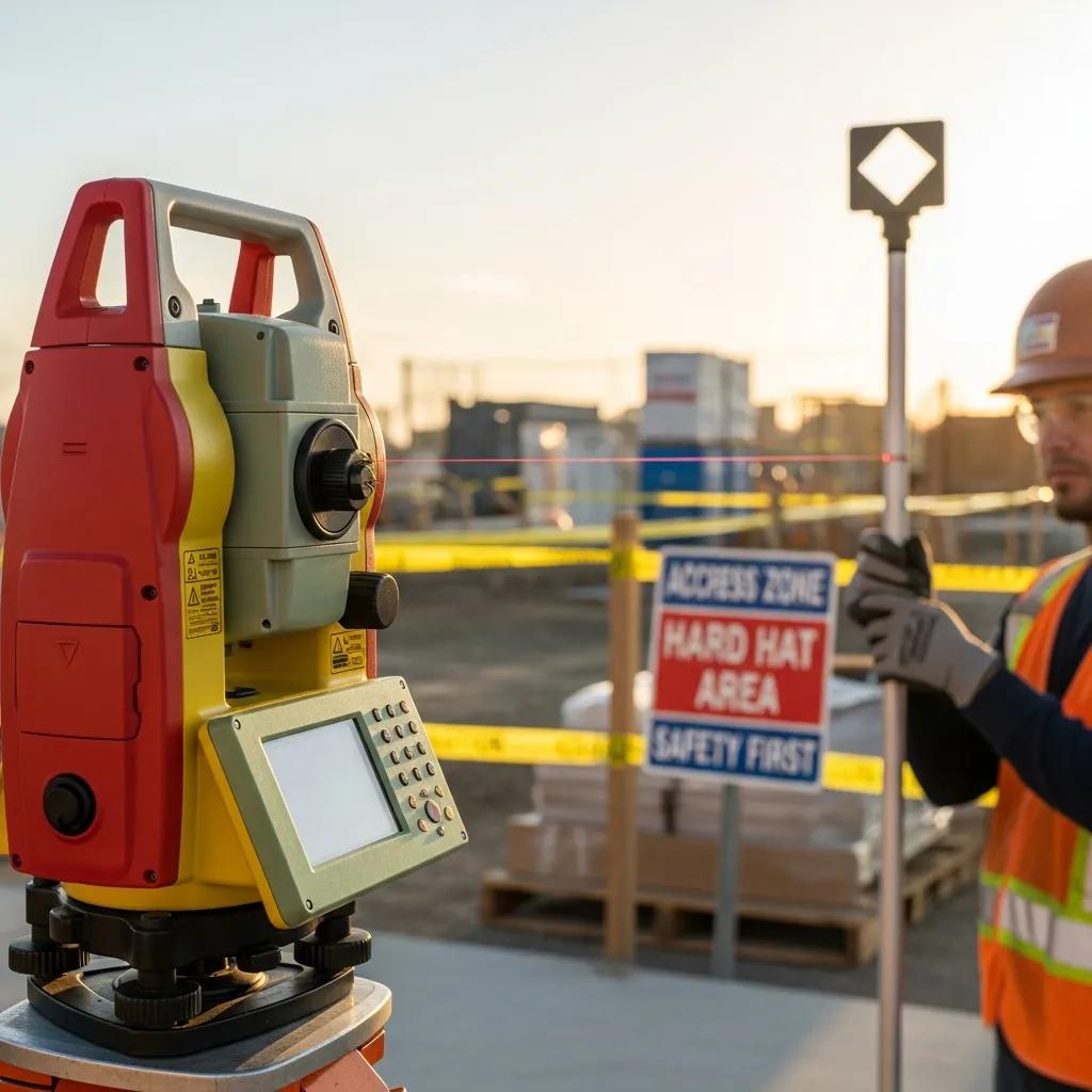
Precision layout technologies, such as robotic total stations and GNSS-assisted setups, translate design coordinates into highly accurate field references that reduce alignment errors, unnecessary rework, and the unsafe adjustments that arise from poor layout. By delivering sub-centimeter placement accuracy for anchors, sleeves, and penetrations, precision layout prevents cascades of corrective work that often expose workers to elevated hazards. The mechanism is measurement fidelity: when model coordinates are executed precisely, installations align correctly, reducing the need for field modifications that can create unplanned exposures. Improved layout accuracy therefore contributes to safer installation sequences, clearer site geometries, and more reliable inspection sign-offs.
A concise comparison clarifies the value of modern layout methods:
- Conventional layout relies on manual transfer and is prone to cumulative error.
- Robotic total station layout automates measurements and reduces human placement errors.
- Verified as-built coordinates from precision surveys support safer handoff and commissioning.
These accuracy gains support safer work sequencing and fewer unexpected on-site corrections.
| Layout Technology | Characteristic | Safety/Accuracy Impact |
|---|---|---|
| Conventional Manual Layout | Tape/offset methods | Higher cumulative error; increased rework risk |
| Robotic Total Station | Automated coordinate transfer | Substantial reduction in human error; millimeter-level placement |
| GNSS-Assisted Layout | RTK corrections for site control | Efficient large-area control; reduces layout time and exposure |
This table highlights how precision layout technologies materially reduce hazards tied to layout errors and field improvisation.
What Are the Safety Benefits of Robotic Total Station Layout Accuracy?
Robotic total stations provide repeatable, high-precision positioning that minimizes misaligned anchors, mislocated penetrations, and the resulting corrective actions that typically expose workers to hazards. When critical components are installed to within millimeters of their design locations, structural and MEP interfaces fit as intended, reducing the need for on-site cutting, temporary works, or unsafe workarounds. Robotic setups also speed verification workflows: crews can confirm coordinates quickly and record as-built positions for QA/QC, ensuring that safety sign-offs are based on measured evidence rather than assumption. These efficiencies lower both risk exposure time and cumulative error across trades.
In practice, accurate layout reduces the scenarios that require climber or confined-space corrections and minimizes interactions in congested zones, improving worker safety across trades. The next subsection explains how that reduction in errors translates to fewer associated hazards.
How Does Precision Layout Reduce Construction Errors and Associated Hazards?
Precision layout reduces construction errors by ensuring installations align with design intent, eliminating many causes of rework that create hazardous conditions such as exposed edges, temporary supports, or congested work areas. Fewer corrections mean fewer instances where crews must perform non-routine tasks under time pressure, which are a leading source of accidents. Precision verification also provides a documented chain of control: measured as-built data supports safe commissioning and ensures that subsequent trades work with accurate references. This continuity shortens the window of exposure to unsafe conditions and stabilizes site logistics for safer daily operations.
Integrating layout verification into safety sign-offs creates a procedural checkpoint that prevents handoffs with unresolved geometric issues, which reinforces safer sequence adherence and reduces unexpected site hazards. The following section reviews complementary digital solutions used for hazard prevention across project phases.
What Digital Solutions Are Available for Construction Site Hazard Prevention?
A range of digital solutions supports hazard prevention at different stages of construction, from pre-construction simulations to field verification and ongoing monitoring. These tools include VDC for sequencing and simulation, BIM for coordination and documentation, 3D laser scanning for as-built verification, IoT sensors for real-time monitoring, and digital twin platforms that consolidate live data for predictive safety analytics. Each solution contributes a different capability: VDC identifies exposures before work, BIM prevents clashes and documents controls, scanning verifies installed conditions, sensors detect anomalous states, and digital twins enable continuous risk assessment. Selecting the right combination depends on project complexity, risk profile, and the phase in which interventions are most valuable.
A practical selection guideline helps teams match tools to needs:
- Use VDC for complex sequencing and logistics-heavy projects to reduce concurrent exposures.
- Deploy BIM for multidisciplinary coordination and compliance documentation.
- Add 3D scanning during rough-in and pre-handover to verify clearances and installed conditions.
These choices should be seen as complementary rather than exclusive; the next subsections explain scan workflows and emerging technologies that augment VDC and BIM.
How Does 3D Scanning Support As-Built Safety Verification and Risk Assessment?
3D laser scanning captures high-fidelity as-built geometry that safety teams can use to verify clearances, detect concealed clashes, and validate installed conditions against model intent. Scans provide a rapid, objective record of congested MEP areas, enabling safety managers to identify insufficient clearances or obstructions that could compromise egress or equipment access. A typical scan-to-safety workflow includes scanning critical zones, generating clash or clearance reports, and producing annotated views for safety briefings and permit attachments. This workflow supports targeted mitigation such as re-routing services or scheduling corrective work during low-exposure windows.
Using scans as part of the verification process reduces surprises during commissioning and enables data-driven decisions about whether additional controls are necessary before occupancy or energization. The subsequent subsection explores new technologies that further extend model-driven safety.
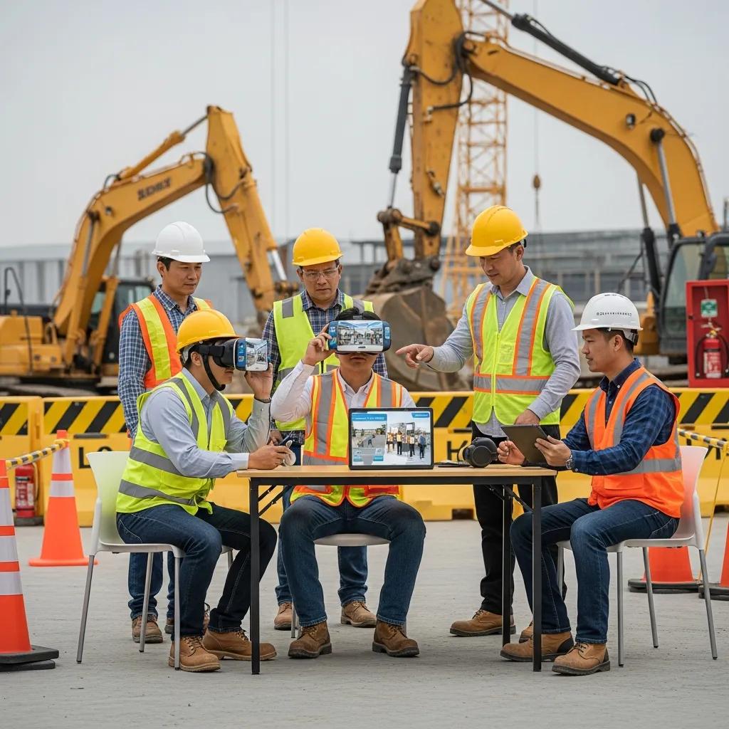
What Emerging Technologies Complement VDC and BIM for Enhanced Safety?
Emerging technologies that complement VDC and BIM include digital twins for continuous risk monitoring, augmented and virtual reality for immersive safety briefings, IoT sensors for live condition tracking, and predictive analytics that fuse model and sensor data to anticipate incidents. Digital twins create a persistent operational model that can absorb sensor feeds and support scenario testing post-construction, while AR/VR allows crews to rehearse complex tasks in a safe virtual environment. IoT sensors detect environmental conditions and equipment states that models alone cannot predict, and predictive algorithms can surface likely failure points based on combined historical and live data. Piloting these technologies on constrained scopes lets teams validate their value before wider rollout.
A recommended pilot approach involves integrating one sensor-driven monitoring use case with model-based simulations to evaluate how live data changes risk profiles and to refine response protocols for field crews. The next major section presents case vignettes that demonstrate measurable safety outcomes from these digital coordination approaches.
Which Case Studies Demonstrate the Impact of Safety Training Programs and Digital Coordination?
Empirical case summaries show that combining safety training with digital coordination reduces rework, prevents clashes that would have required hazardous corrections, and shortens exposure windows through better sequencing. In one illustrative vignette, a model-driven clash detection run identified an interference between a mechanical riser and structural bracing; resolving the clash in the model avoided a field retrofit that would have required work at height and night shifts. In another example, sequencing revisions informed by 4D simulations reduced concurrent crane operations, eliminating several high-exposure periods and improving daily safety briefings. These outcomes translate into quantifiable reductions in corrective hours and fewer high-risk tasks performed under time pressure.
Presenting results in a problem→intervention→outcome format clarifies how digital coordination supplements safety training to produce measurable benefits for crews and project teams.
How Have VDC and BIM Services Prevented Accidents in Complex Construction Projects?
In complex projects, VDC and BIM services often prevent accidents by surfacing installation conflicts and unsafe sequencing long before crews reach the affected zones. For example, a coordinated model revealed that routing for multiple trades would create a congested corridor during final fit-out; changing the sequence and rerouting materials avoided crowded workspaces where fall and collision risks would have spiked. Model-driven mitigation also reduced the need for emergency field fixes, which are high-risk activities due to compressed timelines and improvised controls. The net result in these scenarios is a decrease in unscheduled high-risk tasks and smoother, safer execution.
Lessons from these examples show that early model-based coordination reduces reliance on field improvisation and supports safer training content focused on verified hazards rather than hypothetical scenarios. The next subsection draws lessons from precision layout successes.
What Lessons Can Be Learned from Precision Layout Safety Success Stories?
Precision layout success stories emphasize the value of verification protocols, QA/QC documentation, and clear communication workflows between layout crews and safety managers. Regular layout checks and documented accept/reject criteria prevent installations from proceeding on inaccurate references, which in turn lowers the incidence of corrective tasks that expose workers to hazards. Standardizing verification steps—such as a measured-as-built sign-off before trade handoff—creates a safety checkpoint that prevents cascading errors. Incorporating layout outcomes into safety briefings ensures crews understand the geometric constraints and reduces surprises during installation.
The practical takeaway is to treat layout verification as a mandatory safety control rather than an optional QA activity; doing so embeds accuracy into the safety ecosystem and minimizes exposure to hazardous corrective work. The next section outlines how firms can operationalize these practices by aligning training with digital coordination services.
How Can Construction Firms Integrate Critical Worker Safety Training with Digital Coordination Services?
Integrating safety training with digital coordination requires aligning curricula, roles, and deliverables so that model outputs become training inputs and verification checkpoints become part of safety sign-offs. Start by mapping model-derived hazards to role-specific training modules and toolbox talk content, using visual model snippets and VR walkthroughs where appropriate to make hazards tangible. Establish clear responsibilities: VDC/BIM teams produce annotated model views, safety managers translate those into controls and permits, and field supervisors ensure controls are applied during execution. Metrics such as reductions in rework hours, clash counts, and high-risk tasks performed under time pressure provide validation that training and digital coordination are producing safer outcomes.
A practical, action-oriented checklist helps with initial integration:
- Map model-identified hazards to training modules and toolbox talks.
- Use model visuals and scans in pre-task briefings and permit packages.
- Require layout verification sign-offs before trade handoffs.
- Track safety KPIs linked to model-driven interventions.
These steps create an iterative feedback loop where training is continuously updated as models and field conditions change, which strengthens both prevention and response capabilities.
What Are Best Practices for Combining Training Programs with VDC and BIM Technologies?
Best practices include using model visuals in toolbox talks, creating role-specific VR scenarios for complex tasks, and maintaining synchronized training materials that reflect the latest model updates. Model-based briefings should be scheduled whenever significant sequencing or layout changes occur so crews receive timely, relevant training tied to the work they will perform. Assigning clear ownership for updating training content—typically a joint responsibility between safety managers and VDC/BIM coordinators—ensures materials remain accurate. Finally, use metrics such as reduced corrective actions and improved first-pass installations to validate that training is addressing model-identified hazards effectively.
A short implementation checklist reinforces these practices and helps teams operationalize the link between models and training.
- Create a single-source repository for model snapshots and training artifacts.
- Schedule model-driven briefings at key milestones (pre-mobilization, sequence changes).
- Use measured as-built data to update training content before commissioning.
These actions make training directly relevant to field conditions and reduce surprise exposures during execution.
How Does CCLS Support Clients in Enhancing Safety Through Digital Solutions?
Conway Coordination and Layout Services (CCLS) positions its VDC consulting services, BIM modeling and coordination, precision layout with robotic total station workflows, and 3D scanning offerings as implementation partners that operationalize model-driven safety improvements. As a family-owned and operated business with deep industry experience, CCLS maps VDC hazard simulation and site logistics outputs to safety deliverables—producing annotated model views for toolbox talks, running clash detection with documented resolution workflows, and delivering verified as-built data to support safety sign-offs. CCLS emphasizes precision and accuracy through robotic total stations and scanning, and collaborates with client safety teams to integrate those outputs into training and risk registers.
For firms seeking implementation support, engaging an experienced digital coordination partner can accelerate the translation of model insights into daily operating controls and training materials; CCLS offers consulting engagements to help align VDC/BIM outputs with safety program requirements and onsite verification workflows.
- Engagement Scope: Define model-driven safety deliverables and verification checkpoints.
- Coordination: Integrate BIM/VDC outputs into toolbox talks and permit packages.
- Verification: Use precision layout and scanning to confirm as-built conditions for safety sign-offs.
By combining these services, project teams can convert digital coordination investments into measurable safety improvements and documented assurances for stakeholders.