
Upskilling the Workforce for Digital Construction Tools
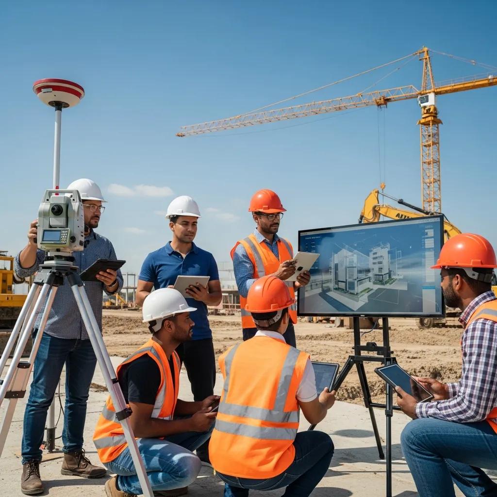
Upskilling the Workforce for Digital Construction Tools: Practical Skills to Improve Field Accuracy and Project Delivery Digital construction upskilling trains both field crews and office teams to use the software, hardware, and data workflows that cut errors, reduce rework, and speed project delivery. The industry skills gap still creates avoidable RFIs, misaligned trades, and messy handoffs; targeted training bridges that gap so teams can apply BIM, VDC, and field-measurement tools with confidence. This guide outlines the digital skills that matter in 2025, how VDC consulting accelerates adoption, and practical best practices for BIM coordination, robotic layout, and 3D scanning. You’ll find which tools to prioritize, the KPIs to measure adoption, and program structures that combine classroom lessons, hands-on practice, and remote mentoring. Throughout, we use current industry concepts—BIM upskilling, clash detection, robotic total station workflows, and cloud collaboration—to give clear, actionable pathways for workforce development and better project outcomes. Conway Coordination and Layout Services (CCLS) translates those training goals into on-site practice and measurable results. As a family-owned provider serving the Southeastern U.S., we pair VDC strategy with hands-on BIM modeling, 3D scanning, and Trimble Robotic Total Station workflows to support adoption across office and field teams. For organizations looking for a structured pathway, CCLS offers role-based curricula, on-site mentoring, and remote follow-up to raise adoption and lower rework; teams can request a consultation or project evaluation to align training with project KPIs. The sections below unpack essential skills, delivery formats, coordination best practices, and real-world results that demonstrate the ROI of upskilling. What Are the Essential Digital Skills for Construction Professionals in 2025? Essential digital skills are the hands-on abilities teams need to make digital tools deliver on accuracy, coordination, and schedule performance. That list includes BIM literacy, clash detection workflows, point-cloud capture and processing, robotic total station operation, cloud collaboration, data literacy for analytics, and a working familiarity with AI-augmented tools. Each skill produces a clear project benefit—clash detection cuts rework, point-cloud processing improves as-built models, and data literacy helps interpret predictive schedule signals. Separating competency goals for field and office roles clarifies training: field crews focus on instrument setup and data capture, while office staff focus on federated models, coordination, and model validation. Targeted training against this skill set yields measurable outcomes like fewer site conflicts, faster RFIs, and better field-to-model feedback loops. Key digital skills for 2025 and why they matter: BIM literacy for field and office: Read and use models accurately to reduce misalignment between drawings and site conditions. Clash detection and resolution: Find and resolve design conflicts early to lower rework and speed coordination. Point cloud capture and processing: Create reliable as-built data for renovations and verification workflows. Robotic total station operation: Translate model coordinates into precise field layout to improve constructability. Cloud collaboration and CDE usage: Maintain a single source of truth for version control and remote coordination. These core skills form the baseline for effective VDC adoption and point to the specific tools and competency levels teams should master next. How to read the skill comparison table and what it shows: Skill What It Enables Project Benefit / Metric BIM literacy Clear model interpretation and accurate markups Fewer RFIs; faster submittal reviews Clash detection Automated conflict discovery and classification Lower rework percentage and faster coordination cycles Point cloud processing Reliable as-built models from scan data Improved renovation accuracy; fewer surprises Robotic total station operation Accurate field stakeout tied to the model Millimeter-level placement; fewer layout errors Cloud CDE proficiency Version control and controlled access Faster approvals and smoother remote collaboration Which digital construction tools should the workforce master? Digital construction tools fall into a few practical categories: modelers, coordination platforms, clash engines, layout instruments, and capture devices—each serving a specific role in the design-to-field workflow. Revit and comparable modelers are for authorship and model handoff, while Navisworks-style tools aggregate disciplines for clash detection and review. Trimble Robotic Total Stations and similar instruments are the go-to tools for accurate field layout. 3D laser scanners and drones capture point clouds for as-built verification and renovation planning, and cloud Common Data Environments (CDEs) handle centralized sharing and version control accessible on field devices. We recommend role-based mini-courses for model authors, coordination workshops for BIM coordinators, and hands-on calibration sessions for field crews to ensure safe, accurate use. Those tool choices inform the training formats: office teams need model-authoring and coordination practice; field crews need hands-on device time. That division prepares teams to work together and leads to the next topic: measurable impacts of BIM upskilling. How does BIM upskilling improve construction project outcomes? BIM upskilling changes how teams scope, detect, and resolve constructability issues before they reach the field—mainly by clarifying data flow and encouraging earlier interdisciplinary validation. Teams that run scheduled clash detection reduce downstream rework and shorten the coordination-to-install cycle; industry data shows RFIs drop when coordination cadence is enforced. When teams combine model-based quantity takeoffs and sequencing, cost and schedule signals get integrated earlier, improving predictability and lowering contingency use. Practical examples include less piping rework when MEP coordinates against structure and faster submittal turnarounds when model revisions are managed in a CDE with clear roles. These measurable gains come from role-based BIM curricula and consistent coordination rhythms that make the model the single source of truth. Stronger BIM skills also improve handoffs to field layout and quality verification, setting teams up to adopt advanced tools like robotic total stations and scanning workflows covered next. How Does VDC Consulting Support Workforce Upskilling in Construction? VDC consulting supports upskilling by delivering strategy, tailored curricula, technology selection, and hands-on mentorship that tie tools and workflows to project KPIs. Consultants assess current capabilities, define role-based competencies, and roll out phased training—starting with fundamentals, moving to coordination practices, and finishing with field-to-model integration. The result is measurable: higher adoption, shorter coordination cycles, and less rework when teams follow proven VDC practices. Delivery modes adapt to project needs; effective programs mix classroom sessions, hands-on instrument training, and ongoing remote mentoring to reinforce learning and solve field
BIM Clash Detection & Resolution in Durham, NC

BIM Clash Detection & Resolution Services in Durham, NC — Expert Coordination That Keeps Projects Moving BIM clash detection and resolution identify and manage geometric and sequencing conflicts inside coordinated digital models so teams avoid costly rework, schedule delays, and installation headaches on site. Below we break down how automated interference checks, federated model workflows, and tolerance-based filters expose hard, soft, and sequencing clashes — and how disciplined resolution reduces change orders and improves constructability on Durham projects. You’ll get a clear look at the detection mechanics, practical clash classifications, an end-to-end coordination cadence, and how tools like Navisworks, Revit, 3D scanning, and robotic layout move the model into the field. We also tie those technical steps to deliverables — clash reports, BCF issue logs, and verified as-built models — so project teams can adopt a repeatable process that lowers risk. After a plain-language primer on why clash detection matters locally, we cover proactive resolution benefits, CCLS’s federated process and toolset, precision technologies we use, and the business outcomes Durham owners and contractors should expect. What is BIM Clash Detection and Why Does It Matter in Durham, NC? BIM clash detection is the automated review of aggregated discipline models to find spatial and sequencing conflicts that would interfere with installation or operation, producing a prioritized list of coordination issues. The process federates Revit/CAD models (and sometimes point clouds), runs rule-based interference checks and tolerance filters, and exports a curated issue log designers and trades can act on to reduce on-site surprises. In Durham — where healthcare additions, commercial renovations, and institutional builds often face tight access, phased work, and overlapping MEP runs — late discovery is costly. Finding clashes in the model preserves schedule and budget by converting potential change orders into coordinated model edits during preconstruction. CCLS applies these same coordination practices on Durham projects — contact us to align scope and cadence with your delivery model. Next, we explain the 3D mechanics of how clashes are found. How Does BIM Clash Detection Identify Conflicts in 3D Building Models? Clash detection compares geometry and object metadata across discipline models to locate physical intersections and clearance violations. Core mechanics include geometric collision tests, tolerance offsets that model required clearances, and rule-based filters that exclude false positives like annotations or temporary items. For example, a duct routed through a structural beam will be flagged: the system assigns a clash type and severity and links it to the responsible discipline via model metadata. Analysts then group related clashes, apply zone or system filters, and prioritize items so coordination meetings focus on the highest-impact work first. Well-designed filters and rule sets cut noise and drive purposeful resolution — which brings us to how clashes are classified. What Are the Types of BIM Clashes: Hard, Soft, and Workflow Explained? Clashes are usually grouped as hard, soft, or workflow so teams know whether an item needs redesign, a small tweak, or schedule/logistics action. A hard clash is a true physical intersection — for example, a pipe occupying the same space as a structural member — and typically requires relocation or redesign. A soft clash indicates clearance or tolerance concerns, such as restricted maintenance access, and is often resolved with minor coordination or spec changes. Workflow clashes expose sequencing problems, like equipment modeled before its supports; these require schedule and logistics fixes. Separating clashes this way helps teams choose corrective actions and log issues in BCF or coordination platforms so detection moves cleanly into documented resolution. Why is Proactive Clash Resolution Essential for Durham Construction Projects? Proactive clash resolution cuts downstream costs by addressing spatial, tolerance, and sequencing conflicts during design and preconstruction rather than in the field. Running iterative clash cycles turns latent design problems into model-level fixes and clarified responsibilities, which reduces RFIs and minimizes change orders that would otherwise cascade into schedule slips. On Durham sites — where constrained access and phased work increase risk — a proactive cadence preserves constructability and protects handover quality. Below we outline the core advantages teams capture through early coordination. Construction teams typically realize three primary benefits from proactive resolution: Fewer rework events and change orders, protecting budget and procurement plans. Schedule protection through early sequencing corrections, avoiding on-site stoppages. Clearer communication and fewer RFIs thanks to shared issue logs and visual viewpoints. These outcomes improve overall project predictability and lead into the cost and schedule impacts described next. How Does Early Clash Detection Reduce Costly Rework and Project Delays? Finding clashes early turns expensive field fixes into model-level decisions, lowering labor and material change-order costs and protecting milestone dates. Industry studies show addressing clashes during design and preconstruction can cut rework by up to 30% because fewer issues reach the site where fixes are costly and disruptive. For example, resolving MEP–structural conflicts in the model on a Durham renovation can prevent a multi-week shutdown of mechanical work and avoid expedited fabrication charges. Regular coordination runs often pay back quickly by trimming contingency spend and preventing sequential delays — which is why teams see measurable savings when clash detection is standard in VDC workflows. In What Ways Does Clash Resolution Enhance Collaboration and Project Efficiency? Clash resolution formalizes collaboration through scheduled coordination meetings, shared federated models, and tracked issue logs that clarify responsibility and deadlines. A typical workflow includes a pre-meeting triage, a multidisciplinary coordination session to assign fixes, and tracked revisions via BCF or a model-based issue tracker to close items — enforcing accountability. Deliverables like prioritized clash reports, saved viewpoints, and updated federated models create a feedback loop that reduces RFIs and improves shop drawing accuracy. Clear ownership and concise deliverables shorten decision cycles and feed verified models into prefabrication and field layout — supporting the model-to-field transfer outlined in the process section. To operationalize these collaboration practices, teams need a repeatable process. The next section outlines an end-to-end clash detection and resolution flow used by coordination specialists. What is the Comprehensive BIM Clash Detection Process Used by CCLS? Our repeatable clash detection process
Your Guide to LEED Certification for Sustainable Buildings

LEED Certification: A Practical Guide to Process, Benefits, and Green Building Standards LEED (Leadership in Energy and Environmental Design) is a performance-driven rating system that sets measurable standards for sustainable design, construction, operation, and maintenance. This guide lays out what LEED requires, who oversees the program, and how project teams turn credits into verifiable outcomes through coordinated models, accurate site layout, and tight field verification. Many certification shortfalls come from gaps between design intent and field execution; disciplined VDC, BIM coordination, and precision layout narrow those gaps and raise the chance of achieving target credits. Ahead you’ll find a plain-language definition of LEED and its rating systems, an overview of core categories and construction actions, a step-by-step certification workflow, the environmental and financial benefits of certification, and practical ways specialized services—like precision layout and model-driven coordination—support compliance with LEED v4.1 and current rating-system requirements. Conway Coordination and Layout Services (CCLS) provides VDC consulting, BIM modeling and coordination, robotic total-station layout, and 3D scanning workflows that link construction execution with LEED documentation and verification needs. Firms that pair model-based documentation with millimeter-accurate layout and as-built verification reduce rework, protect site features, and produce submission-ready evidence for reviewers. This guide prioritizes technical best practices and shows where targeted CCLS services help teams capture credits more reliably and lower certification risk. What Is LEED Certification and How Does It Define Sustainable Building Standards? LEED is a third-party verified framework that evaluates a project’s sustainability across multiple categories using prerequisites and credits. It sets measurable requirements—energy performance, water efficiency, material sourcing, indoor environmental quality—and requires documented evidence to substantiate points. LEED blends design intent, modeled performance, and on-site verification so a project’s projected efficiencies are validated in practice; the result is a performance-oriented certification that signals reduced operational impacts. Knowing who sets the standards and who administers certification matters for registration and submittals, because those organizations define credit language and evidence expectations reviewers apply during assessment. The main LEED rating systems for buildings include BD+C (Building Design + Construction), O+M (Operations + Maintenance), and specialty paths for healthcare and interiors. LEED v4.1 is the current structure many new projects reference. Choose a rating system early: it determines applicable prerequisites, available credits, modeling scope, and site verification plans. Early alignment on the rating system and performance targets lets designers, builders, and coordinators prioritize resources and digital deliverables for reviewer-ready submissions. The next section clarifies which organizations write the standards and which issue certificates—a distinction that affects how teams manage submittals. What Organizations Govern LEED Certification and Its Rating Systems? Two organizations share governance: the U.S. Green Building Council (USGBC) develops and updates LEED standards and credit language, while Green Business Certification Inc. (GBCI) manages project registration, performs technical reviews, and issues certifications. USGBC publishes rating-system versions and guidance—such as LEED v4.1—and GBCI evaluates submitted evidence against credit requirements. This separation means teams use USGBC resources for design intent and GBCI for certification outcomes; effective documentation anticipates reviewer questions to reduce clarification rounds. Understanding these roles helps teams package model outputs, verification reports, and as-built scans in reviewer-friendly formats that speed certification. Because USGBC and GBCI have distinct responsibilities, treat documentation as a compliance deliverable rather than optional marketing. Model-based evidence, clear narratives, and traceable deliverables reduce reviewer clarifications and accelerate certification decisions. Next, we cover how certification levels are determined and how to plan for point targets early in a project. What Are the Different LEED Certification Levels and Their Requirements? LEED issues four levels—Certified, Silver, Gold, and Platinum—based on total points earned from applicable credits and prerequisites. Each tier has a point threshold that reflects progressively higher sustainability performance and usually requires greater investment in energy and water efficiency, materials choices, and innovation. Picking a target level early influences design decisions—mechanical efficiency, renewable investments, and documentation scope—and higher tiers generally need more rigorous modeling and verification to support credited outcomes. Teams should align tier choice with budget, performance goals, and long-term operations to avoid redesign and extra documentation later. During planning, map likely credits to design and construction deliverables and run gap analyses to estimate the effort to reach each tier. That ensures modeling, material tracking, and site verification are scoped to produce the evidence reviewers expect. With certification levels and governance clear, the next section explains core LEED categories and how they translate into construction actions. What Are the Core LEED Categories and How Do They Impact Green Building? LEED groups sustainability into core categories—Sustainable Sites, Water Efficiency, Energy and Atmosphere, Materials and Resources, Indoor Environmental Quality, plus Innovation and Regional Priority—each translating into measurable construction actions and documentation. For builders and engineers, mapping each category to concrete tasks (for example, erosion-control sequencing under Sustainable Sites or commissioning under Energy and Atmosphere) turns abstract credits into executable work packages that can be tracked and evidenced. Tight digital coordination and field verification reduce the gap between modeled performance and in-use results, improving the reliability of claimed credit outcomes. Below is a concise summary of core categories and how they typically show up in construction and documentation. Sustainable Sites: Protect ecology, manage stormwater, and minimize disturbance with accurate layout and erosion control. Water Efficiency: Specify efficient fixtures, optimize irrigation, and verify routing to cut potable water use and wastewater. Energy and Atmosphere: Specify high-efficiency systems, establish commissioning and monitoring, and provide modeled savings. Materials and Resources: Track sourcing, diversion, and reuse with bills of material and as-built records. Indoor Environmental Quality: Use ventilation, filtration, and low-emitting materials to document occupant health and comfort. These category mappings point to coordination tasks and documentation workflows VDC and precision layout support; the sections that follow give examples and an EAV-style mapping for Sustainable Sites. Model accuracy: Improves energy and water credit predictions by reflecting real routing and equipment locations. Field verification: Confirms site features and LID elements are placed to design tolerances and protect stormwater controls. Material tracking: Provides transparent chain-of-custody evidence for recycled or responsibly sourced materials. Commissioning and monitoring: Verifies systems operate as modeled to
Pharmaceutical Facility Layout & Coordination in Augusta, GA

Pharmaceutical Facility Layout & Coordination Services in Augusta, GA — Precise Planning for Compliance and Faster Validation Building or renovating pharmaceutical spaces in Augusta, GA demands millimeter-level layout accuracy, coordinated digital workflows, and strict regulatory alignment to protect product quality and keep validation on schedule. This guide shows how construction layout, BIM/VDC coordination, robotic total station workflows, and reality capture work together to cut rework, support cGMP and ISO cleanroom requirements, and lower schedule risk. You’ll learn which tolerances matter, how layout choices control contamination and staff flow, and what verification outputs regulators expect. We map cGMP, USP 797/800, and ISO drivers to concrete field tasks and verification deliverables, then explain the specialized services and local considerations for Augusta projects. Finally, practical next steps help owners and general contractors scope a layout program, commission digital verification, and move to execution with a clear audit trail. Operational terms — cleanroom layout, BIM coordination, VDC sequencing, robotic total station — are used with real-world examples so teams can prioritize verification work that reduces cost and validation delays. Why Is Precision Critical in Pharmaceutical Facility Construction? Precision is the baseline for compliant processes, contamination control, and predictable schedules. Accurate layout makes sure utilities, pressure boundaries, and equipment anchors match design intent and the acceptance criteria regulators expect. When tolerances are met, airflow patterns, material flows, and validated process sequences commission with fewer deviations — shortening operational qualification and approval cycles. Precise layout also preserves required room adjacencies and segregation schemes from ISO and USP guidance, avoiding costly rebuilds or temporary fixes that can delay batch release. The points below highlight where precision reduces risk and where preconstruction attention delivers the most value. Key considerations that drive precision requirements: Regulatory‑critical interfaces — airlocks, gowning rooms, and pass‑throughs — must align to prevent cross‑contamination and maintain pressure cascades. MEP penetrations and anchor bolt locations typically require millimeter accuracy to avoid rework, equipment misalignment, and validation delays. Coordinated sequencing and verified as‑built records streamline validation and limit audit findings or post‑construction corrective actions. These priorities point directly to the verification workflows and technical services teams use to convert design intent into validated field conditions — the focus of the next section. What Are the Key Regulatory Standards: cGMP, USP 797, and ISO Compliance? cGMP, USP 797/800, and ISO cleanroom classifications set the containment, flow, and documentation expectations layout must enable to protect patients and products. cGMP requires controlled environments and traceable processes, so layout must support validated flows, segregated utilities, and accessible sampling and monitoring points. USP 797 and USP 800 govern sterile compounding and hazardous drug handling; their requirements drive segregation of compounding suites, buffer/ante‑areas, and dedicated exhaust or containment details in the layout. ISO classes (ISO 5–8) map to room adjacency and airflow needs — layout must create the physical relationships and pressure differentials required to meet particulate and microbial targets. Early translation of these standards into layout tasks is essential for architects, MEP designers, and verification teams to coordinate effectively. This regulatory mapping establishes the foundation for a verification program that documents readiness for commissioning and validation. How Does Accurate Layout Prevent Costly Errors and Delays? Accurate layout removes common construction conflicts — misplaced anchor bolts, wrong slab penetrations, and MEP clashes — that otherwise lead to demolition, rework, or equipment reorders and slow validation. For example, a 12–25 mm anchor bolt offset can trigger crane adjustments, baseplate refabrication, or shop redraws that push critical path activities. Digital verification workflows catch offsets during pre‑installation checks and tie field layout to the federated BIM model, shortening the traditional RFI and rework loop. In practice, verified anchor and embed workflows have cut downstream rework and validation hold points by measurable days on time‑sensitive projects. Common error types and mitigations: Anchor bolt misplacement: Pre‑install verification and robotic total station checks reduce replacement cycles and delays. MEP clashes: BIM clash detection with VDC sequencing minimizes on‑site reroutes and fit‑ups. Penetration offsets: 3D scanning of slabs before cutting prevents wrong‑location penetrations and air‑barrier breaches. Preventing these issues requires early coordination, precise field layout, and consistent digital records so corrective actions are minimized and validation readiness is preserved. What Specialized Services Does CCLS Offer for Pharmaceutical Facilities? Our pharmaceutical services translate design intent into verifiable field conditions using a mix of digital coordination and precision layout tools. Core components include BIM/VDC coordination for clash detection and sequencing; Robotic Total Station (RTS) layout for millimeter‑level anchor and penetration verification; 3D laser scanning for accurate as‑built baselines; and cleanroom layout coordination that integrates HVAC zoning, pressure cascades, and personnel/material flows. These services reduce RFIs, accelerate prefabrication, and produce audit‑ready documentation that supports validation. We select the right tools by phase and risk profile — new builds typically begin with RTS and VDC sequencing, while renovations emphasize scan‑to‑BIM workflows to resolve unknowns early. Introductory comparison table of services and typical benefits: Service Typical Application in Pharma Primary Benefit / Metric BIM / VDC MEP clash detection, sequencing, prefabrication planning Fewer RFIs, reduced onsite rework, faster installs Robotic Total Station (RTS) Anchor bolt positioning, penetration layout, hanger placement Millimeter‑level accuracy, fewer corrective actions 3D Laser Scanning As‑built validation for renovations, retrofit modeling Shorter preconstruction, fewer unknowns Cleanroom Coordination Flow planning, pressure cascade integration, HEPA routing Compliance‑ready adjacencies, minimized contamination risk This comparison clarifies when each technology adds value and how they combine to protect schedule and regulatory outcomes. Services list and call to action: BIM/VDC coordination to resolve clashes and define prefabrication sequencing. Robotic total station workflows to verify anchor bolts and critical penetrations with high confidence. 3D scanning to produce registered point clouds that drive retrofit modeling and reduce field surprises. Cleanroom layout coordination to align personnel/material flows, gowning areas, and HVAC zoning. Request a consultation to scope these services, define deliverables, and schedule a site assessment to establish a verification baseline. We’ll outline the right mix of BIM, RTS, and scanning to meet your compliance and schedule goals. Summary: The correct blend of digital coordination and field verification reduces uncertainty,
Accurate Anchor Bolt Verification for Structural Integrity
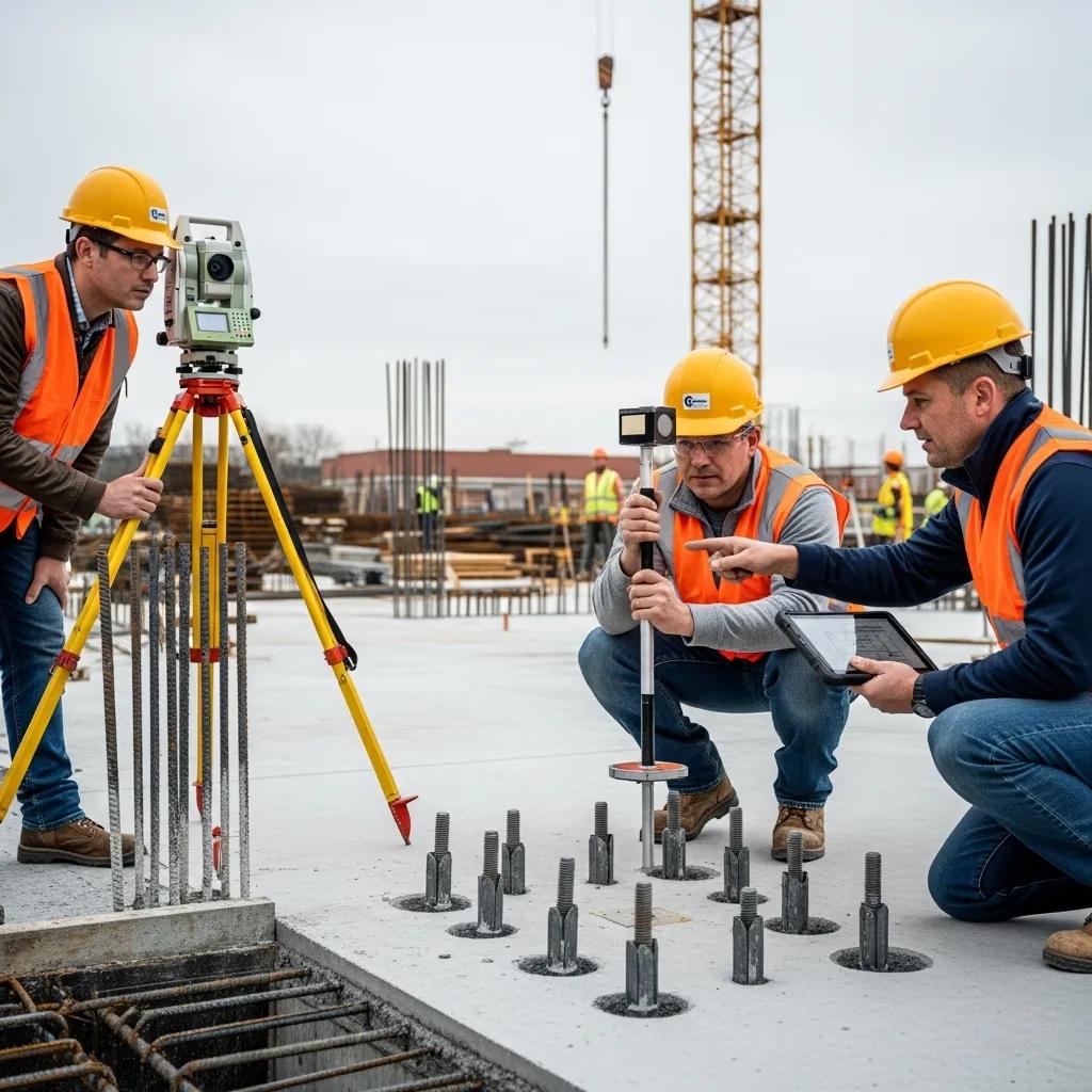
Accurate Anchor Bolt Verification for Structural Integrity: Precision Layout & Inspection Services Accurate anchor bolt verification confirms anchor bolts are located, spaced, and embedded to the design coordinates and tolerances required for reliable load transfer to the foundation. This piece describes how precision layout and verification—backed by modern surveying instruments and coordinated digital workflows—protect structural integrity, cut costly rework, and support code compliance. You’ll find clear explanations of why bolt accuracy matters, the field workflows used to reach millimeter-level results, how BIM and VDC reduce installation errors, applicable standards and tolerances, common installation failures and fixes, plus real-world case outcomes. By emphasizing survey control, model alignment, post-pour as-built surveys, and QA checks, teams can avoid schedule slip and expensive corrective work. The sections that follow break down technical methods, provide practical lists for field crews, and show how focused layout and verification deliver measurable project benefits. Why is Accurate Anchor Bolt Verification Essential for Structural Integrity? Verification proves anchors are where the design requires them to be. When bolt locations match the model, load paths are predictable and base plates and members align correctly. Because bolts carry shear and tension between the superstructure and foundation, even small placement errors can force shimming, introduce eccentric loads, or require retrofit fixes that weaken connections. Verification also reduces schedule risk by catching deviations before steel erection and avoiding expensive re-drilling, epoxy anchors, or engineered remedies. The short list below captures the core benefits and sets the stage for the technical steps that follow. Anchor bolt verification delivers three primary benefits: Safety and load continuity: Correct bolt placement preserves designed load paths and prevents unexpected stress concentrations. Code compliance and inspection readiness: Documented verification shows conformance with structural specs and speeds engineer and authority acceptance. Cost and schedule avoidance: Early detection of errors prevents rework, erection delays, and contractor claims. These benefits lead directly into the mechanics of how placement accuracy preserves stability and what risks arise when bolts are out of position. The next section explains load transfer mechanics and the link between bolt position and structural behavior. How Does Anchor Bolt Accuracy Ensure Structural Stability and Safety? When anchor bolts are placed per design, columns and base plates sit within the intended alignment and axial, shear, and moment loads distribute as expected. Misplaced bolts introduce eccentricities that cause unplanned bending and stress concentrations. Field-verified coordinates reduce the need for shims and avoid retrofit solutions that can compromise connection performance. In practice, holding bolt pattern, elevation, and spacing to millimeter tolerances improves fit-up during erection and lowers the risk of dynamic effects from misaligned connections. These issues matter most under seismic, wind, or heavy-service loading, where small geometric deviations can amplify internal forces and shorten fatigue life. That’s why verification is essential on high-stakes structural systems. What Are the Risks and Costs of Inaccurate Anchor Bolt Placement? Incorrect anchor placement typically creates rework, schedule disruptions, and potential vulnerability when fixes are required after concrete cure or during steel erection. Common remediation—re-drilling, epoxy anchors, or redesigning base plates—carries direct labor and material costs plus indirect losses from delayed trades and inspections. These mistakes can also spark contractual disputes and require extra supervision. In many cases, modest spending on pre-pour layout and post-pour verification saves money by avoiding high-cost corrective actions and keeping erection on schedule. The next section shows how robotic total stations and contemporary workflows deliver the millimeter-level accuracy needed to prevent these risks. How Does CCLS Use Robotic Total Station Technology for Precision Anchor Bolt Layout? Robotic total station workflows combine stable site control, precise instrument setup, and digital stakeout procedures to place and verify anchor bolts within millimeter tolerances. The process starts by building a reliable control network, registering the instrument to model coordinates, staking out embedment templates before pour, and then performing post-pour as-built surveys to record actual bolt positions. That workflow produces annotated plans, point files, and QA reports that demonstrate compliance and support immediate corrective decisions. Below is the field workflow our teams follow to ensure accuracy and traceability. Establish control and register model coordinates: Tie the total station to project control and align to BIM coordinates. Pre-pour layout and verification: Stake out embedment templates and verify offsets before concrete placement. Post-pour as-built survey: Capture actual bolt locations, elevations, and spacing immediately after cure for QA. Deliverables and coordination: Produce annotated drawings, CSV/point files, and as-built documentation for design review. When instruments are calibrated and registration is correct, this workflow achieves millimeter-level results. The table below summarizes common instrument outputs and typical accuracy characteristics from robotic total station workflows used for precision anchor bolt layout. Robotic total station deliverables and accuracy overview: Instrument / Output Characteristic Typical Value Robotic Total Station Positional accuracy ±2–10 mm (project-dependent) Output File Data formats Point file (CSV), annotated plan (PDF), CAD/BIM-ready CSV Field Deliverable Survey report As-built coordinates, elevation, discrepancy log These deliverables let teams make fast, informed decisions and form the basis for model reconciliation and erection planning. The next subsection highlights the practical advantages of millimeter-level accuracy for field operations. What Are the Benefits of Millimeter-Level Accuracy in Anchor Bolt Verification? Tighter accuracy reduces the need for base plate shims, speeds steel erection, and minimizes field changes that drive cost and delay. Precisely placed bolts improve fit-up certainty, shorten inspection cycles, and reduce downtime for trades waiting on structural fit checks. Projects with tight tolerances—precast connections, heavy machinery foundations, or process supports—see immediate benefits because fewer adjustments are required during erection. The result is a smoother handoff between concrete crews and steel erectors, shorter crane and labor mobilization windows, and higher first-time acceptance rates from engineers. Those outcomes directly support project efficiency and owner satisfaction when paired with verified QA deliverables. How Does Real-Time Data Capture Enhance Post-Pour Anchor Bolt Surveys? Real-time data capture connects field measurements directly to stakeholders, enabling immediate quality checks, faster model updates, and auditable as-built records for downstream teams. When survey points flow from the total station into cloud or BIM platforms, engineers can
Virtual Design & Construction Services in Charleston, SC
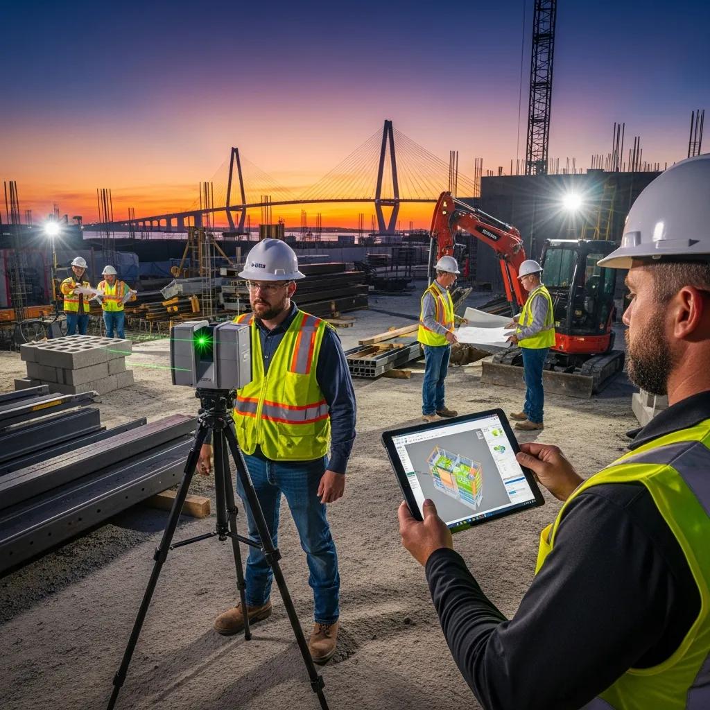
Virtual Design & Construction Services in Charleston, SC: Practical, Complete Solutions to Streamline Your Project Virtual Design and Construction (VDC) combines digital models, field capture, and coordinated workflows to cut rework and keep Charleston projects on schedule. This guide clarifies what VDC is, why it matters for local challenges—like historic renovations and congested MEP runs—and how tools such as BIM, 3D laser scanning, and robotic total stations deliver measurable time and cost savings. You’ll get a clear breakdown of core VDC services, how consulting and training shift contractor workflows, the technical elements of BIM coordination and scan-to-BIM, and why precise layout is critical for MEP and structural trades. Each section includes practical examples, technology overviews, comparison tables, and local use cases so owners, design teams, and contractors in Charleston can evaluate digital construction options with confidence and act on them right away. What Are Virtual Design and Construction Services and Their Benefits in Charleston? VDC is a coordinated process that links model-based design, construction sequencing, and field verification so design intent becomes a reliable basis for site work. It federates discipline models, runs clash detection, and ties model data to schedules and layout—producing clearer constructability reviews and fewer surprises in the field. The payoff is less on-site rework, faster procurement for prefabricated systems, and greater schedule certainty—advantages that matter in Charleston’s historic contexts and tight mechanical spaces. Knowing how each VDC service works helps teams prioritize consulting, BIM coordination, scan-to-BIM, or precision layout where they’ll deliver the greatest value. Below is a straightforward mapping of core VDC components to outcome-focused benefits for quick comparison and decision-making. VDC components and their direct benefits: Component Primary Benefit Example Outcome VDC Consulting Aligned workflows Defined roles, LOD standards, fewer RFIs BIM Modeling & Coordination Fewer clashes Federated models with resolved conflicts before installation 3D Laser Scanning Reliable as-built data Point clouds for renovation verification Robotic Total Station Layout Precise field placement Millimeter-level anchor bolt and hanger layout The table shows how targeted VDC services translate to measurable project improvements and helps teams decide where to invest to lower downstream risk. Next, we outline how VDC reduces time and cost through concrete, implementable mechanisms. How Does VDC Improve Construction Project Efficiency and Cost Reduction? VDC cuts waste and cost by resolving coordination issues in the model, enabling prefabrication, tightening sequencing, and minimizing field rework. Clash detection in federated models prevents on-site conflicts that generate RFIs and expensive fixes. Fabrication-ready models shift work from the field to controlled shop environments, shortening installation windows and reducing labor variability. Linking models to schedules and procurement improves sequencing and staging, decreasing downtime and moving critical-path activities faster. Clash detection: Finds spatial conflicts early so installations proceed smoothly. Prefabrication: Produces fabrication-ready models that reduce field labor and surprises. Schedule integration: Keeps model updates aligned with sequencing to limit delays. Reduced verification cycles: Uses scanned as-built data to validate installations quickly. Combined, these practices shrink contingency needs and make project outcomes more predictable—setting the stage for the specific technologies that power VDC workflows in Charleston. What Technologies Power VDC Services in Charleston, SC? VDC depends on an integrated toolset—modeling, coordination, reality capture, and layout—that closes the loop between design and the field. Autodesk Revit and federated viewers bring discipline models together for clash checks and shop drawings. Navisworks (and similar tools) run clash rules, produce visual reports, and support coordination sessions with trades. 3D laser scanning and point-cloud processing capture accurate as-built conditions. Trimble Robotic Total Stations and related layout systems convert model coordinates into precise field positions for installation and verification. Autodesk Revit: Core for discipline modeling and managing LOD. Navisworks / Coordination Viewers: Federate models and run clash detection. 3D Laser Scanners / Point Cloud Tools: Capture reality data for model reconciliation. Trimble Robotic Total Station: Automates high-precision field layout. Together these tools create a reliable pipeline—model → clash → prefabrication → layout—that lowers uncertainty from design through installation. The next section explains how targeted consulting helps organizations adopt this pipeline successfully. How Does VDC Consulting Enhance Construction Workflows in Charleston? VDC consulting combines assessment, implementation planning, and training to embed digital construction into existing workflows. A typical engagement starts with a workflow assessment that documents current BIM use, communication paths, and LOD expectations, then defines a roadmap for model deliverables, coordination cadence, and QA checkpoints. Implementation covers template setup, clash-management protocols, and integrations between modeling platforms and field layout tools. On-site coaching and training ensure trade partners and project leaders adopt the standards and data routines needed to sustain coordination gains. Effective consulting pairs technical setup with change management: we clarify roles, create deliverable checklists, and provide hands-on training so models drive field actions rather than sit unused. For phased renovations or historic sites in Charleston, consulting identifies which deliverables—scan-to-BIM, LOD 300/400 shop models, or fabrication-ready outputs—are essential to reduce risk. Teams can request a consultation with Conway Coordination and Layout Services (CCLS), a family-owned firm specializing in VDC construction services and precision layout across the Southeast, to arrange a workflow assessment. What Strategic Guidance and Training Are Offered in VDC Consulting Services? Strategic guidance focuses on workflow mapping, defining Levels of Development (LOD), setting clash-management cadences, and training teams on Revit, Navisworks, and field-capture tools. Training can be on-site bootcamps for trades, remote workshops for project teams, or blended coaching tied to live coordination cycles. Consultants create role-based playbooks—what designers, subcontractors, and superintendents must deliver at each milestone—and checklists that align model LOD with procurement and fabrication needs. Training prioritizes practical data flows: how point-cloud scans feed model reconciliation and how layout coordinates are exported for field staking. These organized training activities reduce handover confusion and make model-based verification routine, preparing teams to adopt scan-to-BIM and precision layout practices covered next. How Does VDC Consulting Integrate BIM and 3D Scanning for Project Success? Integrating BIM with 3D scanning starts by capturing accurate as-built conditions, processing point clouds, and reconciling scans with discipline models to confirm geometry and clearances. The pipeline follows scan → registration →
Accurate Structural Layout for Construction Projects

Accurate Structural Layout for Construction Projects: Practical Techniques and Proven Best Practices Accurate structural layout is the disciplined process of placing control points and physical elements so foundations, steel, MEP, and finishes are installed to the design with minimal adjustment. This guide explains how modern measurement workflows, model-driven handoffs, and disciplined QA/QC combine to deliver millimeter-level accuracy that prevents rework, protects structural performance, and keeps schedules on track. You’ll learn why accuracy matters, how robotic total stations and Trimble-enabled workflows cut human error, the role of BIM and VDC in coordination, and how 3D scanning supports as-built verification and renovations. Practical guidance for foundation staking, anchor-bolt verification, and steel erection is included, along with comparison tables that link equipment capabilities and point-cloud outputs to field deliverables. By the end, project teams will have clear, actionable steps to tighten tolerances, fold digital models into field layout, and align trade coordination to measurable accuracy goals. Why is Accurate Structural Layout Critical in Construction? Structural layout sets the baseline geometry every trade uses. When layout is accurate, load paths, connection interfaces, and fabrication fits match engineered assumptions, reducing risk to the structure and avoiding costly fixes. Tight layout control also preserves schedule float by cutting rework and reducing change orders from mislocated elements. The section below summarizes the immediate operational benefits of disciplined layout and highlights common failure modes when control is weak. How Does Precision Impact Structural Integrity and Project Success? Precision controls tolerance stacking so fabricated pieces mate as designed, preserving load transfer and allowing connections to perform as engineered. For example, anchor bolts off by tens of millimeters can require onsite rework, delayed erection, or retrofit holes and shims—introducing fatigue points and unexpected stresses. Likewise, poor slab elevation control can create slab-to-beam conflicts that cascade into MEP clashes and misaligned finishes, affecting schedule and safety. Clear coordination between survey control, field layout, and structural erection is therefore essential for long-term reliability and project success. What Are the Common Risks of Inaccurate Layouts? Poor layout creates predictable risks that erode safety, schedule, and budget unless mitigated by measurement and coordination controls. Typical error sources include manual measurement mistakes, weak control networks, poor model-to-field handoffs, and incomplete QA documentation—each of which can trigger fabrication or erection conflicts. The practical consequences are rework, milestone delays, higher labor costs, added safety exposure during corrective work, and reduced owner confidence. Below are the most common risks and their typical impacts. Rework and fabrication corrections: Misplaced control lines or anchors force field modifications or shop rework that consume labor and material. Schedule delays: Conflicts discovered during installation pause activities and change sequencing, often affecting the critical path. Safety exposures: On-site adjustments and unplanned fits increase risk for crews on elevated or heavy-lift operations. Noncompliance and inspection failures: Layout errors can trigger failed inspections and corrective measures that add time and cost. How Does Robotic Total Station Technology Enhance Construction Layout Accuracy? Robotic total stations combine precise distance and angle measurement with remote control, digital staking workflows, and model connectivity to deliver repeatable, millimeter-level layout on site. They use laser or infrared EDM with automated prism tracking, plus onboard software that interprets model coordinates for direct staking. The outcome is a single-operator workflow that reduces transcription errors, raises layout throughput, and produces digital point records for QA. Below is a focused comparison of practical features and how they translate to field value. Feature Characteristic Practical Value Single-operator control Remote aiming and tracking Reduces crew size and human error during repetitive layout tasks High-precision EDM Millimeter-range measurement tolerance Ensures anchor bolts and gridlines meet fabrication tolerances Software connectivity Import/export of model coordinates Direct handoff from BIM/VDC to field staking workflows What Are the Key Features of Trimble Robotic Total Stations? Trimble robotic total stations offer remote tracking, optional GNSS/RTK integration, real-time software links, and thorough data logging that supports model-driven layout. Remote aiming and prism tracking let one technician stake complex layouts with continuous positional verification. Where GNSS is available, RTK or network corrections improve absolute positions. Onboard or cloud-connected software ingests BIM exports so MEP points, anchor bolts, and structural nodes can be staked directly with digital traceability. These traits limit tolerance drift between model and site and deliver the accuracy modern prefabricated, tight-fit assemblies require. How Does Robotic Total Station Reduce Human Error and Improve Efficiency? Robotic total stations remove common human-error sources by eliminating manual remeasurements, handwritten coordinate transcriptions, and subjective line judgments. Model coordinates transfer directly into staking routines, and digital records capture each point and verification pass for QA audits. Productivity increases because a single skilled operator can run repetitive layout tasks faster than a multi-person manual crew, and repeatability keeps measurements consistent over time. The combination of traceability, speed, and accuracy reduces rework and supports tighter sequencing with prefabrication. When teams are ready to operationalize these workflows, Conway Coordination and Layout Services (CCLS) provides Robotic Total Station Layout services using Trimble equipment for precise MEP layout, anchor-bolt verification, and structural grid staking across the Southeastern U.S. We deliver integrated solutions that pair millimeter-level accuracy with responsive field crews and digital records to reduce rework and accelerate erection schedules. For teams evaluating a technology-first layout partner, CCLS demonstrates how model-based coordinates convert to field control and verified deliverables. What Role Does BIM Play in Structural Layout and Coordination? BIM is the authoritative digital representation of design geometry and metadata that drives coordinated layout references, clash detection, and fabrication-ready outputs for field execution. Embedded coordinate-based definitions let teams extract staking points, anchor locations, and interface geometry directly from the model. This model-to-field linkage reduces interpretation errors and enables trades to resolve spatial conflicts virtually before crews perform physical work. The sections below explain how BIM-led clash workflows operate and how model deliverables support lifecycle asset management. How Does BIM Facilitate Clash Detection and Trade Coordination? BIM-based clash detection finds intersecting elements from different trades inside a shared model, assigns responsibility, and tracks resolution through coordination rounds until conflicts are cleared. The process compares
Augmented Reality (AR) Applications for Construction Sites

Augmented Reality for Construction Sites: Improving Accuracy, Speed, and Safety Augmented reality (AR) overlays digital models and live data onto the jobsite so teams see design intent in place, cut rework, and make faster decisions. This piece lays out how AR differs from virtual reality (VR), the hardware and software used on projects, and practical workflows that tie AR to BIM, VDC, 3D scanning, and robotic layout systems. You’ll find concrete integration patterns for precision layout, clash validation, real-time monitoring, and safety training, plus common adoption hurdles and how to mitigate them. We emphasize measurable outcomes—accuracy gains, time savings, and fewer incidents—and provide clear next steps for piloting AR on active work. Where relevant, we show how Conway Coordination and Layout Services (CCLS) connects VDC, BIM, 3D scanning, and Robotic Total Station workflows to make AR pilots practical and low-risk. What is Augmented Reality in Construction and how is it different from Virtual Reality? In construction, AR is a live system that places 3D model geometry, notes, and sensor feeds into the user’s view of the built environment so crews can validate installations on the spot. It works by registering a BIM or point‑cloud coordinate frame to site control, then rendering model elements on a headset or tablet so users interact with both digital and physical layers at once. VR, by contrast, replaces the physical world with a fully digital scene. That difference makes AR the practical choice for layout checks, trade coordination, and safety walkthroughs where staying in the environment matters. Understanding registration and the component stack clarifies which hardware and software combinations deliver reliable overlays on-site. Overlay accuracy depends on tight registration between model coordinates and site control. Common registration methods—marker-based ties, SLAM (simultaneous localization and mapping), and point-cloud matching—trade speed for precision in different ways. The section below explains the data and devices that underpin those choices. AR delivers three immediate operational benefits for construction teams: Visual verification of as-built conditions against BIM to reduce guesswork during installs. Faster decisions by surfacing coordination issues on-site in real time. Safer, more effective training using contextual hazard overlays while crews stay in place. Those benefits are why AR is being folded into VDC workflows and why firms like CCLS help align AR pilots with existing BIM, scanning, and layout processes to capture value quickly. How does AR place digital information on construction sites? AR puts digital information on site by first capturing the physical environment, aligning a digital coordinate frame to that capture, and then rendering model geometry relative to the registered coordinates so it looks fixed in space. Capture usually uses 3D scanning or photogrammetry to build a point cloud that acts as an anchor; SLAM or control‑point ties then align the model to that anchor. Once registered, AR viewers render BIM elements and metadata—MEP run lists, tolerance envelopes, etc.—on headsets or handhelds. Users interact through touch, gestures, or voice to query properties or measure offsets. The pipeline—scan → register → render → interact—shows why quality input data and tight scan‑to‑model workflows are essential for repeatable AR guidance. What are the key components of AR technology on building projects? AR systems combine three practical layers: hardware, software, and data inputs. Hardware typically includes wearable headsets for hands‑free tasks, tablets or phones for quick checks, and geospatial control equipment (GNSS/RTK or robotic total stations) to anchor coordinates. Software covers AR viewers, BIM‑to‑AR sync tools, and cloud services that stream model slices and sensor feeds. Data inputs are as‑built point clouds, federated BIM models, clash reports, and live IoT telemetry. How these pieces interact—device rendering power, clean model exports, and survey‑grade control—determines whether AR is a visual walkthrough or an actionable layout tool with millimeter tolerances. Knowing these components makes it clearer how AR complements precision layout systems like Robotic Total Stations on complex projects. How does AR improve precision layout and verification on site? AR improves layout and verification by showing BIM layout points and tolerance zones in a user’s field of view while tying those visuals to survey‑grade control and verification tools. The typical flow is: export layout points from the BIM authoring tool, align them to site control (GNSS or Robotic Total Station), then use AR overlays for human‑guided placement or quick checks—reducing back‑and‑forth between model and field. That workflow increases first‑time‑right installs by making deviations obvious and giving crews the context to correct drift before permanent work continues. A practical set of steps teams use to operationalize AR‑enhanced layout follows. Export layout points from BIM and prepare a control file for survey equipment. Establish control ties with GNSS or the Robotic Total Station and deploy registration markers. Load the registered model into the AR viewer and run calibration checks at sample control points. Use AR overlays for placement guidance and the RT Station for final position verification. These steps are most effective when paired with calibrated verification loops and documented tolerances. Conway Coordination and Layout Services (CCLS) integrates Robotic Total Station, 3D scanning, and BIM workflows to build those calibrated pipelines—preparing model exports, executing point‑cloud registrations, and running pilot verification cycles so AR overlays match survey‑grade control and reduce integration risk. For clarity on comparative accuracy and expected use-cases, the table below summarizes common layout approaches and AR’s role. Different layout approaches deliver varying accuracy and practical uses on site. Approach Characteristic Typical Use / Value Robotic Total Station Millimeter‑level accuracy from surveying Final verification and control‑based layout Traditional manual layout Centimeter‑level, manual staking Low‑cost, lower‑precision tasks AR overlay Visual guidance and rapid verification Field‑to‑model checks, visual alignment, reduced rework This comparison shows AR is most effective as a visual and verification layer paired with survey equipment, not as a standalone millimeter‑precision instrument. The next section explains technical integration with Robotic Total Stations for millimeter accuracy. How does AR integrate with Robotic Total Stations for millimeter accuracy? Integration depends on shared coordinate systems and frequent calibration checks so virtual guides align with physical survey points inside tolerance. A practical workflow exports BIM layout points into
Integrating Renewable Energy in Sustainable Buildings

Integrating Renewable Energy into Sustainable Buildings: Precision Coordination and Digital Construction Delivering reliable renewable energy on buildings depends on tight alignment between design intent, structural limits, and field execution. When those elements drift apart, energy performance, timelines, and budgets all pay the price. This article shows how precision coordination and digital construction tools—Virtual Design and Construction (VDC), Building Information Modeling (BIM), 3D scanning, and robotic layout—work together to cut rework and produce predictable results for solar, geothermal, and small wind systems. You’ll get practical workflows for VDC on commercial solar, BIM-driven clash detection for renewable systems, measurable benefits from robotic total station layout, and how point-cloud scans reduce retrofit risk. We also map these methods to concrete uses like building‑integrated photovoltaics (BIPV) and geothermal loop field layout, with an emphasis on energy performance and lifecycle handoff. Conway Coordination and Layout Services (CCLS), led by Nathan Conway, provides VDC, BIM coordination, 3D scanning, point cloud rendering, and Trimble robotic total station layout to support these workflows and offer project-specific coordination and field verification. The article is structured into clear sections covering VDC benefits, BIM capabilities, precision layout technologies, common challenges and mitigations, measurable efficiencies, and practical service applications. How Does Virtual Design and Construction Enhance Renewable Energy Integration? Virtual Design and Construction (VDC) brings models, schedules, and field constraints into a single, coordinated digital process that reduces uncertainty for renewable installations. VDC aligns design models with construction sequencing and exposes clashes and timing conflicts early—reducing change orders and on-site delays for solar and geothermal work. Coordination meetings driven by federated models let structural, MEP, civil, and renewable systems surface spatial and sequencing issues before procurement or layout begins. The result is predictable installation sequences, more prefabrication opportunities, and smoother permitting because constructability is demonstrable. Understanding VDC’s role in sequencing naturally leads to solar-specific workflows that optimize array siting and rooftop attachment coordination. Early clash detection and resolution across structural, MEP, and renewable models. Sequencing and logistics planning that enable prefabrication and minimize site disruption. Integrated scheduling and procurement alignment to speed installation and commissioning. Together, these capabilities make VDC a practical path to fewer RFIs and a cleaner handoff from design into the field. What Role Does VDC Play in Optimizing Solar Power Installation? For solar projects, VDC produces a coordinated rooftop and site model that defines array layout, racking interfaces, and electrical routing. The working loop—design model → coordination session → clash resolution → field verification—cuts clashes between racking, rooftop penetrations, and conduit runs. In practical terms, VDC uncovers obstructions, improves inverter/combiner placement relative to electrical rooms, and sequences deliveries to avoid rework on high-volume commercial installs. Projects using VDC typically report material savings and fewer change orders, with measurable drops in layout-related RFIs. VDC workflows naturally lead into field‑accurate verification—robotic layout and scan‑to‑BIM handoffs confirm the virtual model against as‑built conditions. How Does VDC Facilitate Geothermal and Wind Energy System Coordination? VDC brings subsurface data and foundation constraints into coordinated models to guide geothermal loop siting and small wind attachments. By combining bore logs, horizontal and vertical utility models, and foundation information, VDC prevents trench conflicts and helps sequence bore rig access and spoil handling. For small wind or facade‑mounted turbines, VDC evaluates structural attachment points, wind loads, and maintenance access while coordinating with cladding and rooftop elements. This integrated approach reduces surprises during drilling or excavation and lets design teams optimize loop routing, bore spacing, and foundation reinforcement before mobilization. Effective VDC for subsurface and wind systems sets the stage for precise field layout and verification that meets engineered tolerances. What Are the Benefits of Building Information Modeling for Sustainable Construction? Building Information Modeling (BIM) provides a data-rich collaboration platform for energy analysis, clash detection, lifecycle data capture, and coordinated documentation on renewable projects. BIM attaches semantic metadata to physical components—PV modules, inverters, ground loop segments, conduit runs—so energy simulations and asset information guide decisions from design through operations. The outcome is better‑sized systems, less material waste through prefabrication driven by clash resolution, and complete handover documentation for operations and maintenance. The following table compares BIM capabilities and the value they deliver on renewable projects. BIM Capability Characteristic Stakeholder Value Energy analysis Parametric models paired with performance simulations Optimizes system sizing and placement to maximize yield Clash detection Automated cross‑discipline model tests Reduces field coordination issues and RFIs Lifecycle data tagging Asset metadata for equipment and O&M Simplifies maintenance and long‑term performance tracking How Does BIM Enable Clash Detection in Renewable Energy Projects? BIM enables clash detection by aggregating discipline models—structural, architectural, MEP, and renewable arrays—and running automated collision checks to find spatial conflicts. The process starts with federated models, targets common renewable clashes (PV racking vs. rooftop penetrations, conduit raceways vs. ducts, trench routes vs. utilities), and follows a simple three‑step cycle: import models → run clash tests → assign and resolve issues, then re‑test. Typical clashes include racking interfering with rooftop drains, combiner locations blocking maintenance access, and geothermal loops crossing existing utilities. Resolving these issues early saves schedule days and reduces RFIs and change orders in the field. In What Ways Does BIM Improve Energy Efficiency and Lifecycle Management? BIM supports energy efficiency by enabling early performance simulation that informs equipment sizing, orientation, and control strategies—raising yield and cutting operational waste. Parametric models and simulation outputs—irradiance maps for PV, thermal loads for geothermal—drive iterative placement and capacity decisions. BIM also stores lifecycle metadata for renewable components so operations teams receive asset tags, service intervals, and warranty data at handover. Linking simulation outputs to procurement avoids oversizing or undersizing systems, while embedded O&M data reduces downtime by making maintenance predictable and trackable. How Does Precision Layout Technology Support Renewable Energy Systems in Buildings? Precision layout technology converts coordinated digital models into millimeter‑accurate field placements, closing the loop between BIM/VDC and the built environment. Tools include Robotic Total Stations (Trimble), GNSS/RTK for open sites, laser templates, and 3D‑printed guides for prefabricated assemblies. The workflow—export model → stake from the model with robotic instruments → verify with
Fostering Diversity & Inclusion in the Construction Industry

Building an Inclusive Industry: Practical DEI Strategies and Benefits for Construction At its core, diversity, equity, and inclusion (DEI) in construction is about intentionally recruiting and retaining people from a variety of backgrounds, ensuring fair access to opportunity, and shaping workplaces where everyone can contribute safely and productively. When firms commit to DEI, they expand the talent pipeline, sharpen decision-making on complex projects, and cut operational risk through clearer communication and shared accountability. This article describes how DEI shows up on sites and in offices, outlines the operational benefits for innovation, safety, and financial performance, and offers practical steps firms can take to write policy, train leaders, and measure progress. You’ll find targeted guidance on challenges women commonly face, supplier diversity tactics, workforce development strategies, and specific ways technology—like VDC, BIM, and 3D scanning—can support more inclusive practices. Along the way we highlight examples of how technical coordination and layout services advance DEI goals and provide checklists construction leaders can use right away to improve inclusion and project outcomes. Why Diversity and Inclusion Matter in Construction Diversity and inclusion boost a project’s capacity to solve problems by bringing in different perspectives, strengthen safety culture through more open communication, and stabilize the workforce by attracting underrepresented talent. Teams with cognitive variety tend to produce more practical solutions during design and field coordination, which cuts rework and schedule slippage. Inclusion makes sure those perspectives are heard and acted on, so workers report hazards without fear and tasks get assigned more clearly. Below is a concise rundown of the core benefits contractors and owners should expect. Key benefits of diversity and inclusion: Better Innovation and Problem-Solving: Teams with varied backgrounds generate more coordination options, reducing design conflicts and costly change orders. Safer, More Productive Sites: Open, inclusive communication raises hazard reporting and protocol compliance, which leads to fewer incidents and less rework. Stronger Talent Attraction and Retention: DEI initiatives widen the hiring pool and lower turnover by creating clearer career paths for underrepresented workers. Financial and Competitive Edge: Fewer delays and higher quality translate into cost savings and stronger client reputation. Those outcomes feed one another: better project results encourage inclusive hiring and training, which then drives further operational improvement. Before we move to innovation mechanisms, here’s a compact comparison of how DEI produces value across core performance areas. Outcome Area Mechanism Typical Value/Impact Innovation Cognitive diversity on project teams More design options; fewer late-stage changes Safety Psychological safety and open reporting Lower incident rates; better near-miss capture Productivity Inclusive planning and clear role access Fewer handoffs, less rework, faster schedules Talent Targeted recruitment and development Broader candidate pools and improved retention This table shows how DEI practices translate into concrete project advantages and sets up the next section on how diversity and inclusion drive innovation and problem-solving. How Diversity Strengthens Innovation and Problem-Solving Diversity expands the pool of approaches available to solve technical challenges, which reduces groupthink and surfaces more buildable options during design and construction. When teams include multiple disciplines, cultural perspectives, and different life experiences, they’re more likely to spot constructability issues early and suggest alternative assemblies that save time and money. Industry findings show diverse teams produce a wider set of coordination solutions, raising the chance of selecting options that are easier to build. Practical examples include mixed-discipline coordination sessions that improve sequencing and trade partners proposing prefabrication methods informed by varied workmanship traditions. Those dynamics naturally lead into how inclusive practices convert ideas into safer, more productive sites. How Inclusion Improves Safety and Productivity Inclusion creates psychological safety, improves communication, and standardizes reporting so hazards are identified and addressed earlier. Inclusive toolbox talks, anonymous reporting channels, and role-based access to shared models invite frontline workers to raise concerns without fear. Research and industry reports link stronger employee voice with lower lost-time incident rates and better adherence to work plans—reducing rework and speeding throughput. On-site examples include redesigning sequences after input from diverse crews and adapting equipment ergonomics to reduce fatigue. Those practices close the loop between field reporting and design response and position teams to implement DEI strategies effectively. What Challenges Do Women Face in Construction — and How to Address Them Women in construction often encounter cultural, structural, and procedural barriers that limit entry, progression, and retention unless firms take targeted action. Typical issues include biased hiring and promotion, unequal task assignments, PPE that doesn’t fit, inadequate site facilities, and harassment or exclusionary behaviors. Addressing these gaps requires policy changes, focused training, mentorship, and workplace design updates that support equal participation and clear career pathways. The list below pairs common obstacles with practical solutions firms can apply. Common challenges and practical solutions: Bias in Hiring and Promotion: Use structured interviews and standardized promotion criteria to reduce subjectivity. Role Stereotypes and Task Allocation: Apply role-based competencies and transparent task assignments to ensure fair work distribution. PPE and Facilities Fit: Invest in properly sized PPE and gender-inclusive facilities to remove practical barriers. Harassment and Exclusion: Enforce clear anti-harassment policies, provide safe reporting channels, and act quickly on complaints. Putting these measures in place improves retention and performance and creates a foundation for mentoring and flexible policies that help women advance on projects. Common Gender Biases and Discrimination Issues Typical gender biases in construction include assumptions about physical capability, informal task assignments that limit hands-on learning for women, and promotion practices that rely on subjective referrals instead of measurable competence. Those biases drive higher turnover among women and limit skill accumulation, deepening underrepresentation over time. Discrimination can also appear as microaggressions or exclusion from informal networks that steer career progress. Identifying these patterns lets firms design targeted fixes—blind screening for some roles, objective performance metrics, and inclusive crew rotations. Tackling bias at hiring and allocation points helps retain skilled women and strengthens overall project capability. How Mentorship and Flexible Policies Support Women Mentorship and flexible work policies create practical pathways for women by offering sponsorship, hands-on skill development, and arrangements that accommodate caregiving and life-stage needs. Structured mentorship programs