BIM Coordination for General Contractors in Raleigh, NC
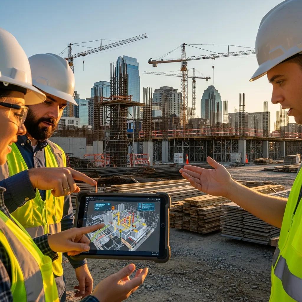
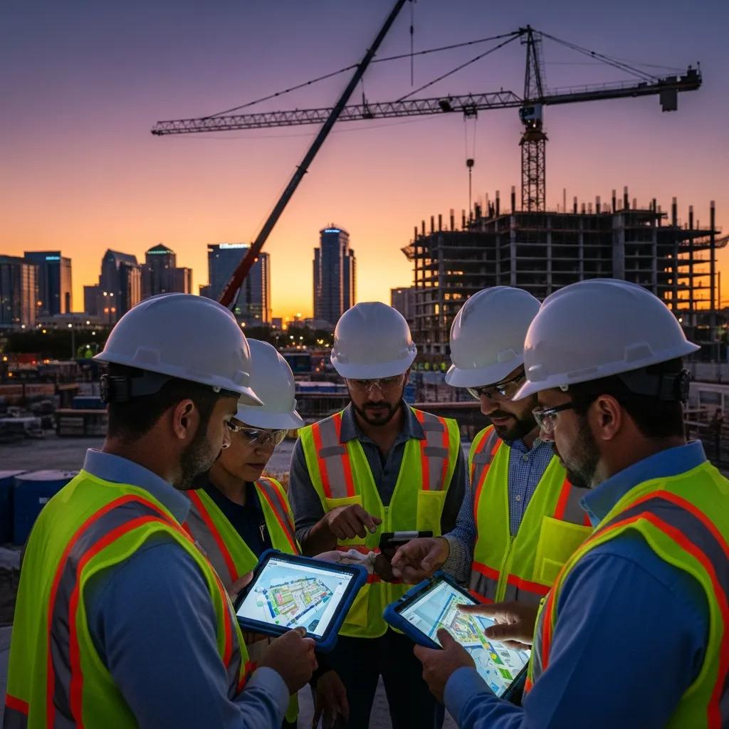
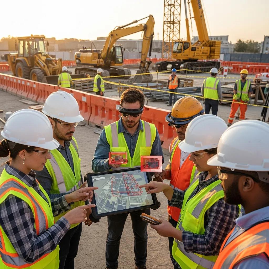
BIM Coordination for Raleigh General Contractors — Practical, Local Solutions for Clearer Builds BIM coordination is the organized process of bringing trade models together, validating geometry, and resolving conflicts before crews reach the field. Done right, it cuts rework, tightens schedules, and gives general contractors a clearer scope of work — especially on Raleigh projects where tight sites and many subcontractors increase coordination risk. This guide explains what BIM coordination looks like in practice, the measurable advantages for GCs, how VDC consulting supports project controls, the layout and scanning tools commonly used here, and how advanced clash detection improves sequencing and prefabrication. We also show how these methods feed into field layout workflows and highlight local service capabilities from Conway Coordination and Layout Services (CCLS). Throughout, we focus on actionable steps and real tools — Trimble robotic total stations, 3D point clouds, and repeatable processes GCs can use to reduce errors and control cost and schedule risk on Raleigh projects. What is BIM Coordination and Why Raleigh GCs Should Care BIM coordination combines discipline models into a single federated model, runs validation and clash checks, and drives timely issue resolution so systems go in with minimal interference. It depends on a shared data environment, disciplined version control, and regular coordination cycles that turn design intent into buildable models. For Raleigh contractors, coordination addresses local constraints — tight urban footprints, phased campus projects, and dense subcontractor teams — by clarifying routing, access, and staging before crews mobilize. The upshot: fewer RFIs, cleaner shop drawings, and a straightforward model-to-field path that supports on-time delivery. These short-cycle wins compound across a project and naturally feed into the sequencing and constructability improvements VDC consulting formalizes. That’s why contractors invest in coordination early and carry it through procurement and field verification. How BIM Integration Improves Project Results Integration drives better outcomes by making clashes and phasing visible before install. Automated clash checks combined with focused coordination meetings reduce field conflicts that cause rework or downtime. Federated 3D/4D visualizations validate access, clearances, and means-and-methods, which shortens approvals and improves subcontractor alignment. Deliverables such as coordinated shop drawings and fabrication packages enable prefabrication, cutting site labor and compressing schedules. Together, these elements lower risk and increase predictability for project managers and superintendents. Equally important: when coordination finds issues, the same models guide layout control and as-built capture so teams close the loop between model and reality. Core Components of Effective BIM Coordination for GCs The essentials are model aggregation, clash detection and issue tracking, LOD and deliverable standards, and structured coordination meetings with clear owners and deadlines. Aggregation pulls Revit or native discipline files into a federated tool (Navisworks or a cloud CDE), enabling checks and visualization. Clash detection combines automated scans and manual reviews to separate hard clashes from softer coordination items, then produces prioritized issue logs with responsibility and timelines. Regular coordination enforces version control and ensures resolved issues update fabrication and layout packages the field uses to build accurately. Put simply: gather models, validate geometry, assign and resolve issues, then release verified coordination models for procurement, prefabrication, and field layout. Key Benefits of BIM Services for Raleigh General Contractors BIM services deliver measurable improvements across cost, schedule, quality, and risk for contractors working in Raleigh’s diverse market. Centralized coordination reduces site conflicts, supports 4D sequencing for logistics, and enables 5D cost scenarios for faster budget decisions. That translates into fewer change orders, more reliable milestones, and smoother handoffs to field teams and trades. Below are the primary contractor-facing benefits and how each adds value. Main contractor benefits from BIM coordination: Less rework and fewer errors: coordinated models catch spatial conflicts early, cutting field corrections. Better schedule performance: 4D sequencing ties model elements to tasks so logistics and the critical path are optimized. Improved cost predictability: 5D ties quantities to budgets for quicker impact analysis on changes. Smoother subcontractor coordination: clear model deliverables reduce RFIs and speed shop drawing approvals. Fabrication readiness: fabrication-ready geometry supports prefabrication and reduces on-site labor. These benefits form the foundation VDC consulting uses to codify digital workflows and QA/QC practices across the project lifecycle. How BIM reduces rework — quick comparison: Rework Reduction Mechanism How It Works Typical Outcome Automated clash detection Finds hard geometric interferences before fabrication Fewer field corrections and on-site clashes Model-based shop drawing review Delivers coordinated fabrication geometry directly to trades Faster approvals and better prefabrication Early constructability review Visualizes sequencing and access limits during design Fewer design-driven change orders Blending automated checks with disciplined review produces the most reliable rework reductions. Next, we explain how VDC consulting embeds these mechanisms into GC project management. Conway Coordination and Layout Services (CCLS) provides local Raleigh support that maps directly to these outcomes. Family-owned and operated, CCLS combines Robotic Total Station layout, VDC construction and consulting services, 3D scanning and point cloud rendering, plus BIM modeling and coordination to put model-driven workflows into field practice. For GCs seeking a consultative partner, CCLS aligns services to project milestones and subcontractor workflows with a focus on precision and collaboration. How VDC Consulting Supports Raleigh Project Management VDC consulting takes BIM coordination further by formalizing digital workflows, defining required data, and advising project managers on process changes that reduce handoffs and errors. At its core, VDC designs workflows: it maps the critical data exchanges between design, procurement, fabrication, and field layout, then prescribes tools, acceptance criteria, and schedules so model updates arrive when needed. For Raleigh projects, VDC also ties sequencing choices to site logistics and permitting timelines to improve milestone reliability. Standardized QA/QC and 4D simulations help managers visualize risk and test alternatives with confidence. Key digital workflows VDC typically optimizes: Model handoff and version control — one source of truth for downstream teams. QA/QC checks embedded in model delivery — prevents late-stage geometry issues. Fabrication and shop drawing readiness — turning coordinated models into prefabrication packages. These workflows reduce information loss between design and execution. Below we show how CCLS applies VDC consulting in practice. CCLS pairs VDC
Effective Inventory Management for Construction Materials
Practical Guide to Construction Material Inventory: Strategies and Technologies for Reliable, Cost‑Effective Control Construction material inventory management combines people, processes, and tools to make sure the right materials arrive where and when they’re needed — with minimal waste, cost, and schedule risk. Effective control depends on accurate quantity tracking, a clear storage hierarchy, and digital visibility so teams avoid over‑ordering, theft, and delays. This guide shows how precision workflows—built around BIM, VDC, and 3D scanning—close the gap between model data and the field. You’ll learn the common causes of inventory drift, the technologies that restore visibility, practical warehouse and laydown‑yard tactics, how precision layout and scanning speed reconciliation, and step‑by‑step actions to deploy digital inventory systems. Throughout, we emphasize material quantity control, warehouse management tactics, and lean construction methods to cut waste and reduce unplanned rework. By the end you’ll have concrete checklists, clear comparisons of storage strategies and technologies, and an implementation matrix that assigns owners to deliverables for pilot‑to‑scale rollouts. What Are the Key Challenges in Construction Material Inventory Control? Inventory control on a construction project fails in predictable ways that reduce visibility and inflate cost. At the heart of the problem is keeping an accurate status of materials across delivery, storage, and installation so procurement and scheduling operate from a single source of truth. Gaps between procurement, site crews, and prefabricators lead to over‑ordering, duplicate orders, and missed deliveries — outcomes that lengthen the critical path and tie up working capital. The list below summarizes the most common challenges and explains why each one directly increases cost or delay. Inventory visibility: Slow or incorrect status updates block timely reallocation and reorder decisions. Over‑ordering and double ordering: Siloed take‑offs and fractured communication create excess stock and storage strain. Theft, damage, and loss tracking: Unsecured laydown yards and unclear custody raise replacement costs and delay work. Kitting and sequencing mismatches: Poorly sequenced deliveries cause rework and repeated handling during assembly. Supplier lead‑time variability: Unreliable delivery windows force inflated safety stock and undermine JIT strategies. Those failures compound: visibility gaps lead to extra orders, which increase storage burden and further obscure inventory status. That’s why disciplined operations and targeted technology are required to restore control. Common Issues in Construction Site Material Management Site material problems show up early as miscounts, inconsistent labeling, and weak storage plans that stop trades from progressing. Count errors at delivery often occur when receiving is rushed or lacks barcode scanning, creating mismatches between physical stock and the procurement system. Disorganized laydown areas and inconsistent labels force crews to hunt for parts or re‑order, increasing labor and delaying critical tasks. Without a single source of truth — where model elements, purchase orders, and site status converge — teams end up repeating verifications and generating rework that wastes material and schedule float. Fixes start small and practical: standardize receiving procedures, capture simple data at handoff, and map storage locations to model coordinates so materials are traceable. These procedural changes remove immediate friction and form the foundation for adding more advanced tracking technologies discussed next. Impact of Inefficient Inventory on Project Costs and Timelines Poor inventory practices show up as measurable cost overruns and schedule slips: rework, idle labor, and carrying costs for excess stock all add up. Rework raises material consumption and labor hours; even a small percentage of extra waste on high‑cost components can erase trade margins. Missing materials push downstream tasks out of sequence and extend the critical path, often triggering overtime or acceleration premiums. Over‑ordering locks up working capital and increases storage and handling expenses, which weakens project cash flow and reduces contingency effectiveness. Quantifying the impact is straightforward: a 3–5% rise in material waste on a trade with expensive prefabricated components can exceed that trade’s margin, and a single missed delivery of a path‑critical item can add days of schedule friction. Those figures illustrate why investments in quantity control and supply‑chain coordination typically pay back through fewer reorders and faster closeout. How Can Technology Enhance Construction Material Tracking and Flow? Technology creates digital links between design data, procurement, and field status so teams can tag, count, and reconcile materials in near real time. BIM enables model‑based take‑offs and tagging, VDC aligns sequencing and delivery windows with the schedule, and 3D scanning confirms physical conditions against the model. Inventory management systems, RFID/IoT, and ERP integrations extend visibility into supplier and finance systems, improving timing and reducing the need for high safety stock. The table below connects core technologies to their inventory functions and expected benefits so teams can make practical ROI comparisons. That mapping helps teams match tools to specific pain points and set realistic expectations for accuracy and time savings. Technology Function Benefit / Metric BIM (model-based take-off) Quantity extraction and component tagging Reduces over‑ordering; accuracy gains typically 5–15% vs manual take‑offs VDC (sequencing & coordination) Delivery sequencing and clash avoidance Reduces laydown time and on‑site inventory via tighter JIT windows 3D scanning As‑built capture and reconciliation Rapid verification of installed materials; early mismatch detection Robotic Total Station Precision layout for install locations Reduces rework from misplacement and supports correct kitting Inventory Management Software (IMS) Real‑time stock status and reordering rules Automates reorder triggers and integrates with procurement/ERP systems With that context, project teams can prioritize pilots where a given technology delivers the largest risk reduction or cost avoidance — and then pick implementation partners accordingly. Role of BIM in Accurate Material Quantification and Tracking BIM improves material quantification by embedding component metadata and enabling model‑based take‑offs that replace or supplement manual measures. A typical flow is: model creation, automated take‑off, tag components with material and supplier attributes, then sync those tags to procurement and inventory systems so scope changes update forecasts immediately. That workflow reduces over‑ordering and lets federated models expose multi‑trade conflicts that would otherwise cause duplicate or incorrect orders. A consistent material data standard — naming conventions and tag protocols — ensures BIM‑derived quantities map cleanly to purchase orders and warehouse locations. Clear data standards and automated workflows shorten
Leveraging Predictive Analytics in Construction Planning
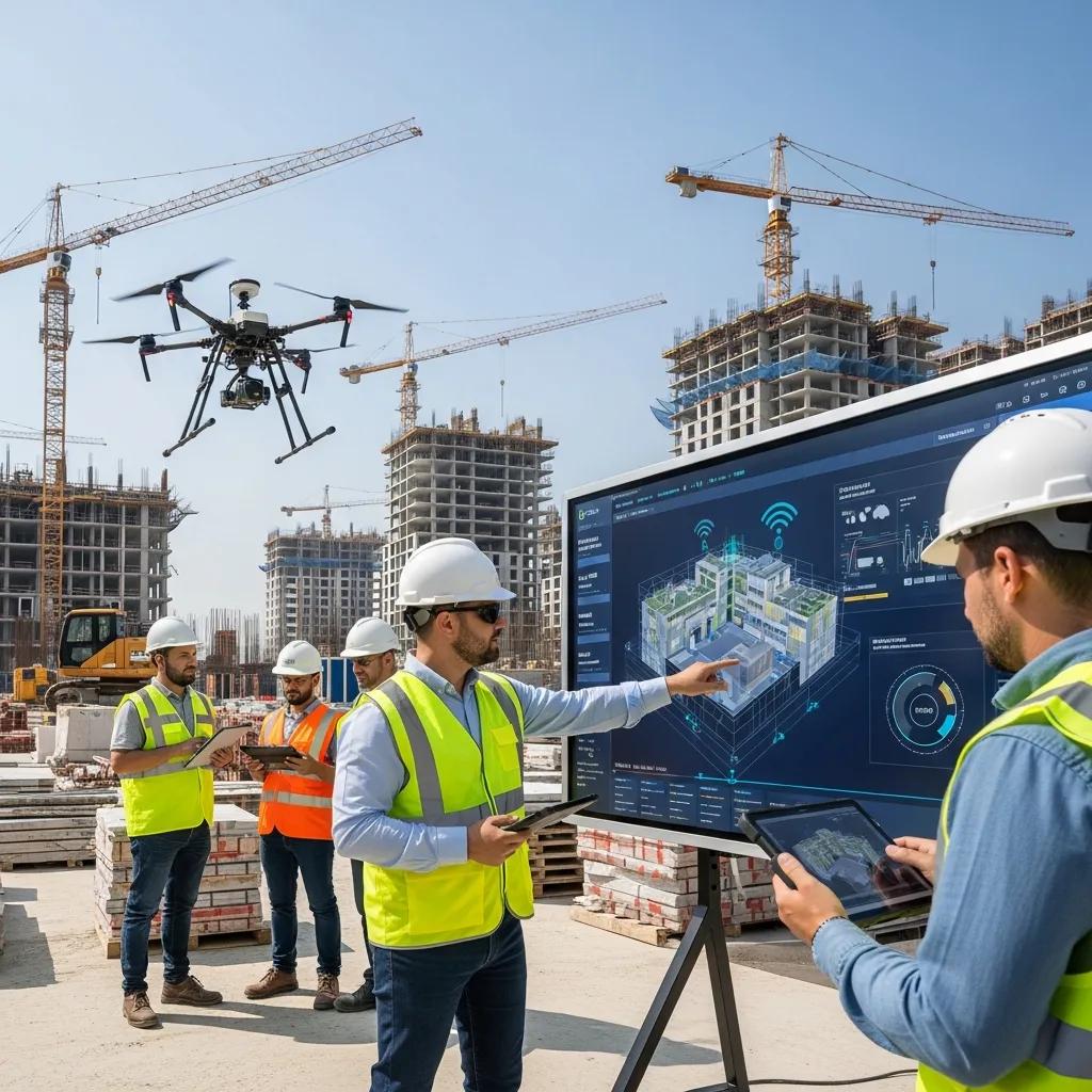
Using Predictive Analytics to Plan Construction Projects: Turning Data into Better Schedules, Budgets, and Outcomes Predictive analytics in construction combines historical records and live site signals to forecast project outcomes, lower uncertainty, and guide timely decisions that keep schedules and budgets on track. This article lays out the core workflow—data capture, model training, forecasting, and action—so project teams can turn scattered information into practical foresight. You’ll learn which data sources matter (BIM, point clouds, IoT sensors, schedule logs), which modeling approaches are commonly used (statistical and machine learning), and how those forecasts reduce rework, improve safety, and optimize resource use. We also show how to fold Virtual Design and Construction (VDC) and BIM into predictive pipelines and share real project results tied to our services. Finally, we highlight emerging trends—digital twins, AI advances, and denser IoT signals—and explain when to bring in Conway Coordination and Layout Services (CCLS) to put predictive insights into practice. Read on for a step-by-step guide to applying predictive analytics on your next project. What is Predictive Analytics in Construction Planning? Predictive analytics in construction planning uses past projects, model data, and live site inputs to forecast future states, flag likely failures, and prioritize fixes before problems appear. The process includes data ingestion, cleaning, statistical or machine-learning modeling, and delivering predictions as risk scores, schedule windows, or maintenance alerts that inform decisions. Success depends on integrating structured BIM metadata, historical schedule and cost records, and live sensor feeds so models can learn the patterns that lead to delays, clashes, or cost overruns. Outputs are probabilistic—P50/P90 schedule forecasts, clash likelihood scores, or maintenance interval predictions—and they drive targeted mitigations like resequencing or early inspections. CCLS’s VDC and BIM services supply the structured models and reality-capture inputs that underpin many predictive workflows. How does predictive analytics use data to forecast construction outcomes? Predictive analytics converts raw site and model inputs into features that statistical and machine-learning models evaluate, producing probability-based forecasts and suggested actions. Typical inputs include BIM attributes, historical productivity logs, equipment telematics, 3D point clouds, and environmental or IoT sensor streams; combined, these signals reveal leading indicators of schedule slips or clashes. Modeling techniques range from time-series regression and survival analysis to supervised classifiers and ensemble methods for added robustness. Outputs usually include ranked risk lists, forecasted completion ranges, and anomaly alerts that teams map to remediation steps. With the right interpretation, project managers can turn probabilistic forecasts into prioritized interventions that reduce downstream impact. Which technologies power predictive analytics in construction? Predictive analytics relies on a technology stack that captures, stores, models, and operationalizes data for construction foresight. Machine learning and AI discover patterns and produce probabilistic forecasts; cloud platforms scale model training and deployment across projects. Digital twins and BIM supply canonical geometry and attribute data to simulate scenarios and detect spatial conflicts, while 3D scanning and point clouds update the twin to reflect as-built conditions. IoT sensors and equipment telematics feed near-real-time performance and environmental metrics that recalibrate models, and robotic layout tools translate predictions into precise field actions. Together these technologies close the loop from detection to on-site execution, improving predictability and cutting rework. What are the Key Benefits of Predictive Analytics for Construction Projects? Predictive analytics delivers measurable benefits across risk management, scheduling, cost control, and quality by turning data into forward-looking insight that enables proactive decisions. Projects using predictive methods typically experience fewer unplanned disruptions because risk signals surface early and interventions are prioritized by probability and impact. Scheduling becomes more reliable through probabilistic forecasts and resource-optimization suggestions, which cut idle time and accelerate critical-path tasks. Cost control improves with early detection of cost drivers and scenario-based what-if analysis that limit contingency spending and reduce rework. Quality benefits from model-driven clash detection and reality-capture validation that prevent field corrections and improve final outcomes. Below is a simple comparison showing how each benefit maps to a predictive mechanism and the expected result. Benefit Area Predictive Mechanism Expected Outcome Risk Management Hazard scoring from historical + sensor data Fewer incidents; prioritized mitigations Scheduling Probabilistic schedule forecasts (P50/P90) Reduced mean delay days; improved predictability Cost Control Cost-forecasting models tied to model attributes Lower contingency spend; fewer change orders Quality & Rework Reduction Clash probability from BIM + point clouds Fewer on-site corrections; faster turnover Each benefit links to a concrete predictive mechanism—when teams act on those outputs, measurable outcomes follow. Next, we look specifically at site safety and risk handling. How does predictive analytics improve risk management and safety? Predictive risk management improves safety by surfacing high-risk activities, locations, and sequences before incidents occur, allowing preventive controls and targeted training. Models ingest near-miss logs, activity durations, BIM spatial metadata, and live sensor readings to produce site risk heatmaps and activity-specific scores. Safety teams then prioritize inspections, redesign hazardous sequences in virtual simulations, or schedule work during safer windows based on forecasts. Running sequences against a digital twin reduces exposure by validating constructability and sequence feasibility before crews arrive. Translating probabilistic risk into prioritized actions lowers incident rates and builds a defensible record of proactive management. In what ways does predictive analytics optimize project scheduling and resource allocation? Predictive scheduling applies probabilistic models and resource-leveling algorithms to generate forecast windows and allocation recommendations that reduce idle time and compress schedule variance. Models analyze historical crew productivity, equipment utilization logs, weather patterns, and BIM task dependencies to identify likely completion ranges and resource bottlenecks. Outputs can include prioritized shift adjustments, crew reallocations, or pre-positioning of equipment for critical activities that commonly drive delays. By converting predictions into tactical moves, teams prevent cascading delays and improve on-time performance. The next section explains how VDC and BIM create the structured data these workflows need. How Does CCLS Integrate VDC and BIM to Enhance Predictive Construction Planning? At CCLS we integrate Virtual Design and Construction (VDC) and BIM to produce reliable, queryable datasets that fuel predictive analytics and support data-driven decisions. Our VDC consulting establishes data governance, naming conventions, and model workflows so predictive models receive consistent
Healthcare Facility Layout & Coordination in Miami, FL
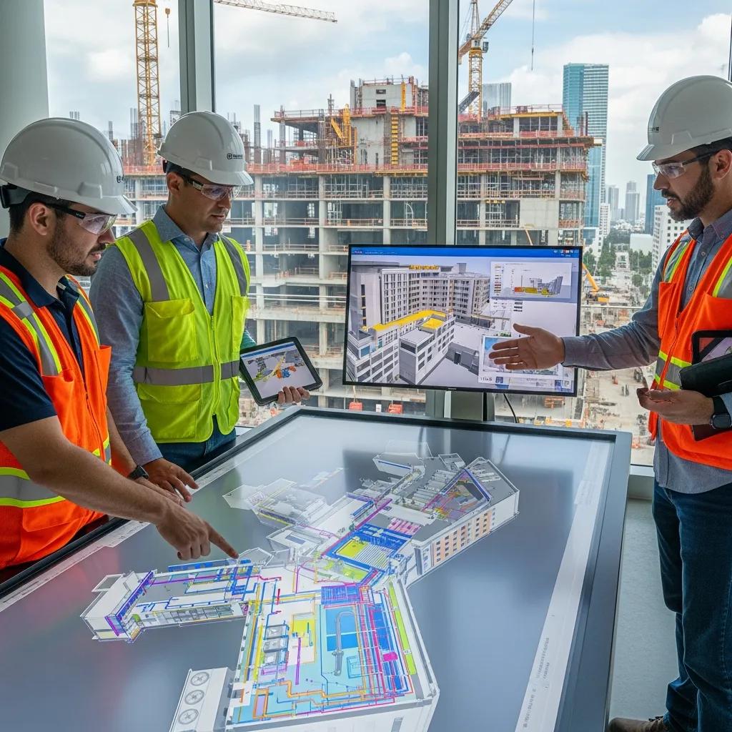
Healthcare Facility Layout & Coordination in Miami, FL: Precision BIM & VDC for Reliable, On‑Schedule Delivery Healthcare projects in Miami require tight coordination across complex MEP systems, specialized medical equipment, and strict regulatory controls. Modern digital construction tools—BIM and VDC—give teams a practical way to manage that complexity. This article shows how model-based coordination, clash detection, and precision field layout cut rework, improve schedule certainty, and protect patient‑safety systems during hospital builds and renovations. You’ll find clear, actionable benefits of hospital BIM coordination, how VDC consulting improves sequencing and logistics, the role of Robotic Total Station and 3D scanning in as‑built verification, and project-management practices that deliver resilient, maintainable facilities. We also address Miami‑specific concerns—climate resilience, infection‑control during construction, and sustaining operations—and how technology-driven workflows respond to those challenges. Our aim is straightforward guidance owners, architects, contractors, and facility managers can use to reduce cost, tighten schedules, and simplify handover. What Are the Benefits of BIM Coordination for Miami Healthcare Facilities? BIM coordination brings discipline models together so teams can find and resolve spatial conflicts before work reaches the field. Regular clash detection runs and shared, coordinated models produce clearer installation sequencing and verified routing for critical MEP systems. That model-first approach reduces field rework, shortens install times, and creates audit-ready documentation for regulators. The direct outcomes are fewer RFIs, lower change‑order risk, and more predictable procurement and prefabrication—critical on complex hospital jobs. Those measurable improvements explain why BIM coordination is central to delivering healthcare projects in Miami. BIM coordination provides several high‑impact benefits for hospital work: Stronger MEP coordination: Federated models expose routing conflicts before crews arrive, avoiding costly field fixes. Less rework and fewer change orders: Early detection of clashes reduces corrective work and downstream cost creep. Schedule gains and prefabrication readiness: Sequencing models enable off‑site fabrication and faster on‑site assembly. Regulatory traceability and documentation: Model-based deliverables support inspections and infection‑control verification. Those gains flow into smarter procurement and faster operational readiness. The table below maps coordination capabilities to measurable project impacts. Different BIM coordination capabilities map to specific project benefits and measurable impacts. Coordination Feature Mechanism Project Benefit Clash detection cycles Automated spatial analysis of federated models Fewer RFIs and reduced on‑site clashes Sequencing and 4D simulation Time‑linked model simulations Shorter critical‑path durations and improved prefabrication MEP coordination workflows Discipline‑specific routing and clearance checks Reduced rework and on‑time equipment installation This comparison shows how specific BIM features produce reliable outcomes on healthcare projects. For Miami teams needing practical support, Conway Coordination and Layout Services (CCLS) offers BIM coordination focused on clash reduction, prefabrication sequencing, and deliverables designed for regulatory review; contacting our team clarifies how these capabilities apply to your project. How Does BIM Improve Hospital Layout and MEP Coordination in Miami? BIM improves hospital layout by creating a federated environment where architecture, structure, and MEP systems are validated together against program and equipment needs. We run scheduled model federations, clash detection passes, and coordinated markups so discipline leads can resolve conflicts before crews mobilize. The outcome is spatial certainty: medical gas, HVAC risers, and imaging equipment pathways are checked for clearance and serviceability, reducing interruptions during construction. Effective BIM workflows depend on standard naming conventions, aligned levels, and a model‑of‑record practice that feeds coordination meetings and produces traceable clash reports and RFIs. That model-driven certainty supports better scheduling and prepares the project for prefabrication and modular assembly—reducing labor exposure and site congestion. What Are the Cost and Schedule Advantages of BIM for Miami Medical Facility Projects? BIM shifts discovery from the field into the model, cutting unplanned labor and change orders that cause overruns. In practice, iterative coordination and prefabrication planning lower rework costs and compress installation timelines through staged sequencing and lean delivery. The approach ties 4D schedules to procurement-ready model deliverables, enabling earlier long‑lead ordering and off‑site fabrication. Owners typically see higher labor productivity, fewer retrofit hours, and clearer acceptance criteria at turnover. Those benefits shorten commissioning windows and smooth the transition to operations—important where downtime and disruption affect patient safety and finances. How Does VDC Consulting Enhance Medical Facility Construction in Miami? VDC consulting applies a digital‑first construction strategy that combines modeling, simulation, and logistics to optimize how healthcare facilities are built. VDC turns design intent into executable work packages by aligning sequencing, site logistics, stakeholder coordination, and constructability analysis. Practically, that means fewer surprises during installation, better staging of equipment and materials, and stronger collaboration between clinical teams and contractors. VDC also validates infection‑control phasing and temporary works so critical hospital operations remain protected during construction or renovation. VDC consulting typically delivers these outputs and outcomes: Clash detection and coordination reports: Prioritized lists and tracked resolutions for discipline conflicts. Construction sequencing and 4D simulations: Visualized work phases and logistics to reduce site congestion. Stakeholder coordination packages: Aligned clinical access plans, shutdown windows, and turnover checklists. Those deliverables translate into measurable reductions in site stoppages and RFI volume and form the basis for bids that reflect constructible designs ready for prefabrication. For Miami projects needing tailored VDC support, Conway Coordination and Layout Services provides consulting that focuses on clash mitigation, prefabrication sequencing, and stakeholder‑driven documentation—prioritizing actionable outputs that align digital deliverables with field execution. What Role Does Clash Detection Play in Miami Healthcare VDC Services? Clash detection identifies and manages spatial conflicts inside federated discipline models. In healthcare VDC services it protects patient‑safety systems by preventing improper routing of medical gases, HVAC, and electrical services. We run rule‑based checks to find hard and soft clashes—such as structural penetrations interfering with ductwork or equipment clearances conflicting with ceiling systems—and rank issues by severity for resolution. The result is fewer site stoppages, clearer installation sequences, and documented approvals that feed commissioning and regulatory review. Regular clash runs tied to coordination meetings lower RFI volume and create audit trails that demonstrate due diligence in protecting clinical infrastructure—especially important when construction happens alongside ongoing operations. How Does VDC Optimize Pharmaceutical Facility Layouts in Miami? VDC optimizes pharmaceutical layouts by modeling process flows, cleanroom separations, and utility
Benefits of Apprenticeship Programs in Construction

Why Apprenticeships Matter in Construction: Building Skilled Trades, Digital Competency, and Workforce Resilience Modern construction apprenticeships pair structured, on-the-job trade training with focused classroom instruction to produce work-ready crews for today’s tech-enabled jobsite. This piece outlines how apprenticeship pathways let participants earn while they learn, gain recognized credentials, and move along clear career ladders — while simultaneously helping employers close persistent skills gaps by embedding digital competencies like VDC and BIM. You’ll see the direct benefits to apprentices and employers, how tools such as robotic total stations and 3D scanning fit into curricula, and practical steps for designing programs that track measurable outcomes and create promotion pathways into leadership. Throughout, we reference terms like trade skills training, on-the-job training construction, VDC apprenticeship, and robotic total station training so practitioners and decision‑makers can map these concepts to real workforce-development solutions. What Are the Core Benefits of Construction Apprenticeship Programs? Apprenticeships give trainees a structured route to competence by combining classroom instruction with supervised field work. Programs that use competency milestones and tied wage progression reduce the need for remedial training, boost retention, and create transparent career ladders. Employers gain a steady talent pipeline and lower recruiting and turnover costs, while apprentices avoid student debt because they earn income as they train. Together, credentialing, mentorship, and hands-on practice develop technical skill, safety habits, and the teamwork and communication that support advanced specializations like VDC or robotic layout. Different stakeholders realize different upside from apprenticeships; the table below summarizes core benefits, primary beneficiaries, typical outcomes, and common metrics used to measure success. Apprenticeship benefits by stakeholder and measurable outcome: Benefit Who Benefits Typical Outcomes Metrics Earn-while-you-learn Apprentices Steady income during training; reduced student debt Apprentice retention rate; wage progression Hands-on competency Employers & apprentices Job-ready skills; less on-site supervision Time-to-productivity; competency milestone completion Credentialing Apprentices & industry Recognized certificates; career mobility Certification pass rates; promotion counts Retention & loyalty Employers Lower turnover; clearer succession pipeline Annual turnover rate; internal promotion rate This comparison makes it easier for employers to prioritize the metrics that matter as programs scale and evolve. Hands-on development comes through defined milestones and supervised practice — which leads naturally to how on‑the‑job training and wage progression are structured. How Do Apprenticeships Provide Hands-On Training and Earn-While-You-Learn Opportunities? Apprenticeships mix field mentorship with classroom lessons so trainees practice real trade tasks under experienced supervisors and get immediate feedback. Programs break skills into competency milestones — for example, foundation layout, interior finishes, or basic BIM navigation — and link wage steps to demonstrated ability, aligning pay with learning progress. Mentors (often journeypersons) reinforce technique, safety, and quality, which reduces costly rework and raises workmanship standards. Progress is tracked through logged hours, competency assessments, and periodic reviews so both apprentices and employers have clear signals about readiness and next steps. Those on-site learning mechanisms create credential pathways that move apprentices into higher-responsibility roles — a topic we cover next. What Role Do Apprenticeships Play in Skilled Trades Training and Career Advancement? Apprenticeships create visible career ladders from entry-level apprentice to journeyworker and onward to supervisory or technical specialist roles by combining certified competencies with documented project experience. Trade and digital credentials validate skills for employers and open routes into roles such as foreman, BIM coordinator, or VDC lead. Employers benefit from lower dependence on outside hires, cost savings, and stronger institutional knowledge. Succession planning becomes deliberate as apprentices progress through milestones that include both technical and leadership training, preserving skills as veteran workers retire. Clear career mapping reduces ambiguity for apprentices, encourages completion, and strengthens the long-term stability of the construction workforce. How Does Integrating Advanced Technology Enhance Modern Construction Apprenticeships? Adding BIM, VDC, robotic total stations, and 3D scanning to apprenticeship curricula teaches digital construction skills that cut errors and speed field work. These technologies build transferable competencies — model navigation, clash detection, scan-to-BIM verification — that improve coordination between office and field and make apprentices immediately more useful on projects. Training ranges from software labs to supervised equipment use on site, reinforcing the link between virtual models and physical installation. The result: fewer RFIs and rework, and workflows that support prefabrication and faster installs. Below is a concise comparison of common technologies, the skills they teach, training modality, and the impact on project outcomes. Technology comparison for apprenticeship training: Technology Skill Taught Training Modality Impact on Outcomes Robotic Total Station Precision layout operations Field supervision, calibration labs Reduced layout errors; faster setup BIM / VDC Model coordination; clash detection Software labs, coordination meetings Fewer RFIs; improved prefabrication fit 3D Scanning / Point Cloud As-built capture and verification Scan exercises, processing workshops Accurate record; streamlined as-built deliverables This table shows how specific tools map to teachable skills and measurable improvements in quality and schedule to guide curriculum design. On-the-job equipment time plus lab practice accelerates adoption. Firms that combine classroom work with field mentorship see higher competence and faster technology uptake. For example, apprentices who operate layout instruments and read point clouds can validate model-to-field alignment, improving quality control and cutting installation delays. Employers integrating these tools should codify competency milestones and provide supervised practice so trainees gain both technical skill and on-the-ground judgment. Because equipment access is often the limiting factor for applied learning, many firms partner with VDC consultants and technology providers to structure practical training — which leads into the concrete benefits of tools like robotic total stations and 3D scanners. What Are the Benefits of Training with Robotic Total Stations and 3D Scanning? Training on robotic total stations and 3D scanners teaches precision measurement and as‑built documentation that reduce layout errors and speed verification on site. Robotic layout instruction focuses on calibration, instrument control, and interpreting field offsets to minimize cumulative tolerances and rework. 3D scanning covers capture best practices, point‑cloud registration, and producing verification deliverables so teams can quickly compare design intent with installation. When apprentices master these tools, project teams see fewer layout disputes and faster acceptance of prefabricated systems because measurements are repeatable and
Attracting New Talent to the Construction Industry

Attracting New Talent to the Construction Industry: Practical Strategies and Modern Career Paths Bringing new people into construction means recasting familiar workforce challenges as opportunities: high-tech, career-focused roles that resonate with younger candidates. This guide lays out why recruiting the next generation matters, how technology and training create clear career ladders, and what firms can do now to build a future-ready workforce. You’ll get a straightforward look at the root causes of the labor gap, how VDC, BIM, 3D scanning, and robotic layout reshape daily work, and which recruitment and training tactics produce the best hires. We map education pathways, employer-branding moves, diversity initiatives, and digital channels so construction leaders can turn tech adoption and workforce development into real recruiting advantages. What Are the Key Challenges in Attracting Young Talent to Construction? At heart, the industry faces a supply problem driven by demographics, perception, and a widening skills gap. Retirements remove institutional know-how, old stereotypes make the field look low-tech, and faster technology adoption raises expectations for digital skills. These forces combine to squeeze hiring, inflate labor costs, and threaten schedule reliability. Solving the problem takes aligned work across recruitment messaging, training programs, and on-site experiences that clearly show career progression. Below we break down the main causes and how they immediately affect project delivery and staffing. Common root causes that explain recruitment difficulty include: A maturing workforce: many skilled tradespeople are retiring while fewer new workers enter the pipeline. Perception gaps: construction is often seen as low-tech, risky, or offering limited upward mobility—off-putting to tech-minded candidates. Skills mismatch: modern projects demand digital construction competencies that many new entrants lack. Left unaddressed, these factors increase hiring pressure, push up labor costs, and undermine schedule certainty. The next section looks at the demographic trends driving the shortage and why timing is critical for replacement planning. How Does the Aging Workforce Impact Construction Talent Shortage? The industry’s median age has climbed, creating a wave of retirements that sharply increases replacement needs and erodes trade-specific knowledge. When seasoned operators and supervisors leave, their tacit expertise—sequencing, quality checks, site risk judgment—goes with them, forcing rapid upskilling of newer workers. Teams without timely replacements see schedule slips, more rework, and heavier reliance on short-term labor. Employers should forecast retirements, capture institutional knowledge, and accelerate competency-based training to stabilize crews and protect productivity. These steps make pipeline-building and apprenticeships urgent, not optional. What Perception Gaps Affect Recruitment in Construction? Many young people still picture construction as mainly manual labor in unsafe conditions with few promotion paths. Today’s sector includes tech-forward roles that mix fieldwork with digital coordination—and that message isn’t landing. Companies that highlight model-based coordination, precision robotic layout, and AR site reviews win candidates who want purposeful, skill-building careers. Recruitment messaging must replace outdated images with concrete examples of tech-enabled tasks, clear promotion routes, and real safety improvements to attract digitally literate talent. How Do Advanced Technologies Transform Construction Careers? Advanced tools create hybrid roles that blend field execution with digital coordination, raising skill requirements and career potential. Technology removes repetitive manual work and opens paths like digital construction coordinator, BIM specialist, and robotic layout technician—roles that are steadier and more skilled. These changes also improve safety and project outcomes through precision and early clash detection, making the day-to-day less physically punishing and more engaging. Below is a concise comparison of core technologies, the skills they demand, and the career benefits they create to help hiring managers decide where to invest in talent development. Different digital construction technologies require distinct competencies and lead to different career outcomes. Technology Key Skill Set Typical Roles Immediate Career Benefit Virtual Design & Construction (VDC) Model coordination, sequencing, visualization VDC coordinator, construction technologist Cross-discipline coordination experience that speeds leadership progression Building Information Modeling (BIM) Modeling, clash detection, data management BIM modeler, BIM coordinator Transferable digital skills that boost marketability and mobility 3D Scanning & Point Cloud Processing Laser scanning operation, point cloud registration 3D scanning technician, scan-to-BIM specialist Specialized, high-demand niche with fast on-site-to-model turnaround Robotic Total Station Layout Robotic instrument operation, precision surveying Robotic layout technician, field survey operator Millimeter-level accuracy that reduces rework and improves safety This comparison shows how each technology maps to jobs and practical advantages, helping teams prioritize hiring and upskilling. The next pages dig deeper into VDC and BIM and how they shape daily work. What Role Does Virtual Design and Construction Play in Modern Jobs? VDC centralizes model-based coordination, sequencing, and visualization so teams can reduce rework and streamline field execution. VDC specialists run clash detection, build installation sequences, and create visual guides that forepersons and crews use on site—mixing office-based problem solving with practical field impact. Roles that expose entry-level staff to VDC create fast learning cycles that accelerate competency and retention, so VDC experience is a powerful recruitment differentiator. How Are Building Information Modeling Skills Shaping Future Careers? BIM skills—model creation, coordination, data hygiene, and interoperability—are now currency in construction. Practitioners move from modeler to coordinator to VDC manager, picking up supervisory responsibilities and cross-trade influence. Training focused on tools, standards, and model-based workflows produces hires who can turn plans into executable sequences and cut onsite ambiguity. For recruitment, promoting BIM career ladders signals a tech-rich pathway with clear promotion mechanics and transferable skills. Which Strategies Bridge the Skills Gap in the Construction Workforce? Closing the skills gap takes a layered approach: apprenticeships, employer-led upskilling, academic partnerships, and accessible micro-credentials so entrants gain both trade and digital competence. Priorities include competency-based apprenticeships with embedded digital modules, on-the-job VDC/BIM exposure, and aligning school curricula with employer needs. These steps shorten time-to-productivity and create visible career ladders that attract tech-oriented candidates. The table below compares program types to help firms pick the right mix. Comparing program types clarifies which approaches deliver quick reskilling versus long-term progression. Program Type Target Skill Outcome Apprenticeship with Digital Modules Core trade + BIM/VDC basics Long-term progression and credentialed competence Short Courses & Micro-credentials Specific software or hardware skills Fast upskilling and immediate role fit Industry
Implementing Water Conservation in Construction Projects
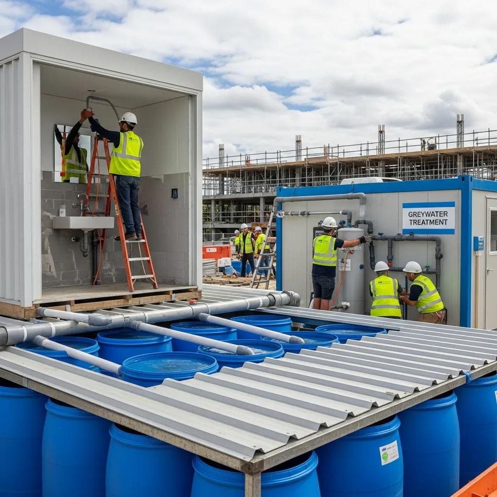
Practical Guide to Water Conservation in Construction: Techniques, Technologies, and Benefits Water conservation in construction means designing, installing, and operating building systems so they use less potable water while meeting performance and code requirements. This guide explains why conserving water on projects matters—given regulatory pressure and constrained resources—and summarizes practical solutions like rainwater harvesting, greywater recycling, low-flow fixtures, permeable paving, and closed-loop site systems. We also cover how digital coordination—BIM for water infrastructure and VDC for water-efficiency workflows—turns designs into accurate installs, and how precision layout tools reduce rework during plumbing and tank placement. Read on for core techniques, the role of VDC and BIM, environmental and economic benefits, LEED and code considerations, best practices and case-study approaches, and how robotic total stations plus clash detection preserve system performance. Where useful, Conway Coordination and Layout Services (CCLS)—a family-owned provider of VDC consulting, BIM coordination, robotic total station layout, and 3D scanning—is referenced as a practical partner for implementing these measures efficiently. Key Water Conservation Techniques for Construction Water-conservation techniques in construction use design, technology, and operational practice to cut potable water use and reduce runoff. They capture non-potable sources, lower fixture demand, and manage stormwater on site to reduce freshwater withdrawals and treatment loads. The benefits include measurable utility savings, stronger site resilience, and potential green-building credits. Below is a concise comparison of primary approaches, common applications, and installation notes to help teams choose the right mix for commercial and institutional projects. This table compares leading water-conservation technologies and practical attributes. Approach Typical Use-Cases Typical Savings / Installation Notes Rainwater harvesting (roof-top) Irrigation, toilet flushing, process non-potable use Can reduce outdoor potable demand by 20–80%; requires tank, filtration, overflow design Greywater recycling systems Toilet flushing, landscape irrigation in commercial/healthcare Saves 20–50% of domestic water; needs plumbing segregation and treatment unit Low-flow fixtures & fittings Lavatories, showers, kitchens Immediate potable reductions with simple retrofit/installation; low capital cost Permeable paving & SuDS Stormwater infiltration, runoff reduction Reduces runoff peaks; may reduce need for detention infrastructure Closed-loop construction site water systems Dust control, equipment washdown Reuses site water to limit potable use during construction; requires temporary tanks/filtration Combining capture, reuse, and demand reduction produces the largest net savings. That sets up the next section on system design details: tank sizing, treatment levels, and trade coordination for reliable field installation. How Rainwater Harvesting Supports Sustainable Buildings Rainwater harvesting captures runoff for non-potable uses, cutting municipal demand and reducing stormwater volumes. Core components are roof catchment, gutters/downspouts, first-flush diverters, filtration, storage tanks, and distribution loops to irrigation, toilets, or process uses. Correct tank sizing depends on roof area, local rainfall, intended uses, and site footprint; designs must include overflow, service access, and code compliance. On dense commercial sites, integration affects structural loads, underground utilities, and construction sequencing—areas that benefit from early, model-based coordination and layout planning. Placement and filtration choices influence maintenance and long-term performance, so model tank footprints early and reserve maintenance access in structural plans. Proper plumbing and storm integration reduces cross-connection risk and simplifies commissioning. These planning steps naturally pair with greywater strategies to broaden available non-potable supply. Benefits of Greywater Recycling Systems Greywater recycling captures lightly used water from lavatories, showers, and some sinks, treating it for toilet flushing and irrigation to reduce potable demand. Typical systems include source-separated plumbing, a treatment train (screening, biological or membrane processes depending on reuse), storage, and a non-potable distribution loop. Treatment is matched to intended reuse and local regulations. Benefits include lower utility bills, reduced sewer flows, and improved on-site resilience—especially where water restrictions or high utility rates apply. Greywater systems require careful plumbing segregation and coordination with mechanical and plumbing trades to avoid cross-connections and ensure maintainability. Because greywater ties directly into building plumbing and controls, detailed modeling and clash-checking reduce field changes. These coordination needs illustrate the value of BIM and VDC workflows for routing, prefabrication, and sequencing. How VDC and BIM Improve Water Efficiency on Projects BIM for water infrastructure and VDC for water efficiency create a single, authoritative digital model that all trades use to design, coordinate, and execute water-conserving systems. BIM captures components and spatial relationships for clash detection, accurate quantity takeoffs, and prefabrication of pipe racks, tanks, and manifolds. VDC adds sequencing, logistics, and stakeholder coordination so model intent is realized in the field. The result: less rework, fewer water-related delays, and clearer documentation for LEED water credits and permitting. The following table maps BIM/VDC capabilities to practical outcomes that improve water-conservation delivery. BIM/VDC Feature Function in Water Systems Benefit / Outcome 3D coordination & clash detection Identify interferences between tanks, piping, and structure Prevents field rework and schedule delays Model-based quantity takeoff Generate accurate material lists for plumbing and storage Reduces waste and supports prefabrication Sequencing & logistics (VDC) Plan installation order and temporary services Minimizes on-site freshwater use and staging conflicts Point-cloud integration Validate as-built against the model after installation Ensures system performance and handover accuracy These capabilities show how model-driven workflows raise installation accuracy and operational performance, which leads into BIM-specific practices that support precise infrastructure design and prefabrication. How BIM Modeling Enables Precise Water Infrastructure Design BIM encodes geometry, metadata, and performance criteria into a coordinated digital twin that all stakeholders reference through design and construction. Models capture routing for potable and non-potable loops, tank footprints, pump and valve schedules, and access clearances—details that enable interference checks and prefabrication to reduce on-site welding and joint work. Level-of-detail (LOD) expectations for water systems typically require component geometry, connectivity, and manufacturer data to support prefabrication and installation; meeting these LOD standards reduces surprises in the field. The model-to-layout workflow converts BIM coordinates into field control points, guiding precision layout teams to place tanks and piping accurately. When BIM informs fabrication and layout, projects see shorter installation times and smoother commissioning. Those model deliverables also create a defensible record for compliance and performance verification, which naturally leads into the VDC consulting role that coordinates these deliverables. VDC Consulting’s Role in Optimizing Water Conservation VDC consulting coordinates
BIM Modeling & Coordination in Orlando, FL
Precision BIM Modeling & Coordination in Orlando, FL — Optimize Your Construction Projects Precision BIM modeling and coordination bridge design intent and field reality to cut rework, tighten installation sequencing, and simplify long‑term asset management for Orlando projects. This guide explains BIM and coordination in the Central Florida context, how model-driven workflows lower clashes and schedule risk, and which technical deliverables teams expect during planning, fabrication, and turnover. You’ll get a clear overview of core processes—clash detection, federated models, scan‑to‑BIM, and VDC consulting—plus practical steps to onboard a local BIM partner. The examples map to common Orlando work types like renovations, commercial construction, and MEP‑heavy projects, and highlight technologies that enable millimeter‑level field accuracy. If you manage design, trade coordination, or facilities in Central Florida, this article gives the decision criteria, workflows, and outcomes to evaluate BIM modeling and coordination services. Finally, we outline how to request a consultation with Conway Coordination and Layout Services (CCLS), a family‑owned team serving Florida and the Southeastern U.S. What is BIM Modeling and Coordination in Orlando Construction? BIM modeling and coordination create a single, data‑rich model that represents architectural, structural, and MEP systems so teams can find and resolve conflicts before installation. By federating Revit discipline models and referencing point‑cloud as‑builts, coordination establishes one source of truth for clash detection, 4D sequencing, and fabrication‑ready outputs. That centralized model integration plus regular coordination cycles reduces site surprises and speeds procurement and prefabrication. Below are three core benefits that explain why Orlando teams rely on BIM coordination. Clearer constructability decisions: Coordination reveals clashes and routing conflicts early, preventing costly onsite rework. Faster sequencing and prefabrication: 4D planning and fabrication models compress install windows and reduce trade dependencies. Accurate as‑built baselines: Scan‑to‑BIM point clouds deliver millimeter‑level documentation for renovations and retrofits. Together, these elements help teams overcome Orlando’s fast schedules and retrofit complexities. Local practitioners commonly pair model coordination with field layout verification to confirm installed systems match the digital model. Conway Coordination and Layout Services (CCLS) brings field‑proven layout and VDC coordination practices to Orlando projects with regional experience and exacting standards. How does BIM enhance construction planning and execution? BIM turns design geometry and metadata into actionable construction intelligence used for clash resolution, sequencing, and procurement. Clash detection—via Navisworks, federated Revit workflows, or similar tools—finds spatial conflicts across MEP, structural, and architectural models so issues are resolved virtually instead of on site. 4D planning ties model elements to schedule logic so sequencing issues surface before crews mobilize, reducing critical‑path delays. Better visualization through coordinated views and model walkthroughs aligns owners, designers, and contractors, cutting RFIs and misunderstandings that lead to change orders. These capabilities improve constructability and handover quality, which brings us to the specific coordination components Orlando projects need. What are the key components of BIM coordination for Orlando projects? Core components include disciplined model authoring, federated model management, scheduled coordination cycles, clash reporting, and field verification using point clouds and layout equipment. Consistent families and shared parameter conventions are essential so discipline models merge cleanly without losing metadata. Regular coordination meetings—run against defined clash thresholds and tracked with action logs—produce resolved model iterations and clash reports that feed shop drawings and fabrication. Typical deliverables are federated Revit/Navisworks models, clash matrices, annotated markups, and as‑built updates after installation. Adding precise field layout tools and point‑cloud validation ensures the model reflects actual site conditions and prepares teams for fabrication‑ready modeling, described in our service offerings below. Why Choose Expert BIM Coordination Services in Orlando, FL? Engaging an experienced BIM coordinator reduces risk, shortens schedules, and improves constructability through standardized workflows tuned to Orlando projects. Specialists deliver repeatable coordination cadences, disciplined clash management, and model‑to‑fabrication practices that cut onsite rework and change orders. Local knowledge matters: retrofits, hospitality builds, and institutional projects have recurring coordination patterns and compliance needs that experienced providers anticipate. Here are the primary reasons to hire an expert BIM coordinator for Orlando construction. Lower project risk by resolving issues virtually and reducing RFI‑driven delays on site. Cost and schedule savings from prefabrication‑ready models and streamlined procurement. Field accuracy through integrated 3D scanning and layout verification technologies. Those advantages translate into measurable project improvements. The next section explains how BIM specifically reduces rework and schedule risk for trade coordination and fabrication workflows. How does BIM reduce costly rework and project delays? BIM reduces rework by catching spatial conflicts and system mismatches before fabrication or installation, avoiding expensive shop reruns and corrective labor. By focusing clash detection on high‑impact issues—like penetrations or structural obstructions—teams can redesign routing or adjust coordination zones while still in the model. Fabrication‑ready models provide accurate coordinates and annotations for shop drawing production, cutting markups and reruns. Field verification with 3D scanning and layout instruments confirms tolerances before install, closing the loop between the digital model and the finished installation. These practices shorten punch lists and keep projects on schedule, addressing the time pressures common in Orlando work. What local Orlando construction challenges does BIM address? Orlando projects commonly face compressed schedules, complex MEP systems in hospitality and healthcare, and frequent renovations that demand precise as‑built knowledge—challenges BIM workflows are built to solve. For fast builds, 4D sequencing and prefabrication reduce labor coordination and enable parallel workstreams. Renovations benefit from scan‑to‑BIM deliveries that provide verified existing‑condition models and prevent surprises caused by undocumented conditions. Projects with many subcontractors gain clarity from disciplined coordination deliverables—federated models and clash reports—so trades clearly understand scope and spatial interfaces. These targeted solutions show how BIM delivers practical, local value and lead into our catalog of services. What Comprehensive BIM Services Does CCLS Offer in Orlando? CCLS offers a full suite of BIM and VDC services tailored to Orlando and Central Florida projects, including MEP BIM coordination, structural and architectural modeling, scan‑to‑BIM capture, clash detection cycles, fabrication‑ready modeling, and precision field layout. We combine office coordination with field verification—such as Trimble Robotic Total Station layout—to ensure model accuracy translates to installed systems. Typical deliverables include federated Revit models, clash reports, fabrication coordinates, and
Proactive Hazard Identification & Mitigation in Construction
Proactive Hazard Identification and Mitigation in Construction: Practical Safety Planning and Risk Management Proactive hazard identification intentionally finds, analyzes, and addresses site risks before crews arrive—using digital models and precision field layout to cut incidents and avoid costly rework. By combining early design review, virtual simulation, and on‑site verification, hazards are exposed in a controlled setting and resolved through design or sequencing changes. This article explains how proactive work differs from reactive responses, how Virtual Design & Construction (VDC) and Building Information Modeling (BIM) strengthen safety planning, and how precision instruments like robotic total stations and 3D scanning close the model‑to‑field loop. We provide a stepwise safety‑plan framework—model-based hazard simulation, constructability reviews, job hazard analysis, and site verification—plus practical lists, comparison tables, and checklists to help safety managers, BIM coordinators, and project leads turn detection into durable mitigation while improving schedule reliability and cost predictability. What is Proactive Hazard Identification and Why is it Crucial in Construction? Proactive hazard identification means finding potential safety risks during pre‑construction and early design so design choices, sequencing, and controls remove or reduce hazards before fieldwork starts. The approach depends on data‑rich models, coordinated multidisciplinary reviews, and scenario testing to reveal clashes, access issues, and temporary‑works needs. The primary payoff is fewer incidents, less rework, and more predictable schedules. This contrasts with reactive approaches that respond after an event—incurring higher costs and disruption. Proactive programs create a feedback loop: model findings inform permit scopes, JHAs, and daily briefings so crews act on prioritized controls. The next section shows how early detection prevents accidents by enabling concrete design and sequencing interventions that remove hazards at the source. Proactive hazard programs typically deliver three core benefits: Improved schedule reliability through fewer field reworks and coordinated sequencing. Lower incident rates by resolving design and access hazards before construction. Cost avoidance from eliminated clashes and reduced corrective scope. Those outcomes show why teams should invest earlier in hazard discovery and mitigation instead of absorbing higher downstream costs and safety exposures. How Does Early Hazard Detection Prevent Construction Site Accidents? Early detection prevents accidents by exposing causal chains—design conflict → constrained access → improvised workarounds—and removing root causes through design or procedural changes. When simulations reveal fall openings or poor egress during a virtual walkthrough, teams can adjust edge protection, reroute staging, or reschedule tasks to avoid exposing crews during high‑risk activities. The path from detection to prevention includes identification, assignment of mitigations, model verification, and field validation during layout and installation. Tracking near‑misses, corrective actions, and rework hours demonstrates how early detection lowers incident frequency and improves crew behavior. Effective detection converts abstract risks into prioritized, verifiable tasks crews can implement safely. What Are the Common Types of Construction Hazards to Identify? Construction projects consistently present hazard categories that should be included in proactive reviews: falls from height, struck‑by incidents, caught‑in/between exposures, electrical risks, environmental hazards, and ergonomic/manual‑handling stresses. Each hazard class shows up differently across phases—design choices may create fall exposures during shell work, while staging decisions can create struck‑by risks during heavy lifts. Proactive measures map to these categories—design‑for‑safety fixes, sequencing changes, exclusion zones, temporary works, and focused training—so mitigations are applied before crews adopt unsafe workarounds. Prioritizing these categories in early reviews ensures high‑consequence hazards are remediated during project development. How Does Virtual Design and Construction Enhance Construction Safety? Virtual Design and Construction (VDC) improves safety by using coordinated digital models and process simulations to expose hazards, optimize logistics, and validate sequencing before fieldwork begins. VDC integrates multidisciplinary models, runs scenario simulations, and organizes stakeholder reviews so abstract risks become actionable mitigations. The result is fewer on‑site conflicts and clearer execution plans. With VDC, safety teams run virtual walkthroughs, simulate lifts, and stress‑test access routes so hazardous conditions are either designed out or controlled with temporary works. Feeding VDC outputs into daily planning and JHAs closes the loop between office coordination and field behavior, improving traceability and risk communication. VDC delivers safety improvements through three principal workflows: Hazard simulation and risk visualization to identify pinch points and access issues. Clash detection and coordination to remove physical conflicts that drive unsafe workarounds. Site logistics modeling to reduce exposure during material handling and heavy lifts. These workflows convert model intelligence into project controls. The table below summarizes key VDC capabilities and their expected safety outcomes. Different VDC capabilities map to distinct safety outcomes: VDC Capability Core Attribute Direct Safety Outcome Hazard simulation Scenario‑based model runs Identifies pinch points and fall hazards before construction Clash detection Automated geometry checks Eliminates installation conflicts that cause rework and unsafe fixes Site logistics modeling Sequence and layout planning Reduces material handling exposures and equipment interference This table clarifies how each VDC function targets a measurable safety outcome and helps teams prioritize coordination work. CCLS approach to VDC Consulting: CCLS turns model findings into field‑ready mitigations through a repeatable process: Develop integrated digital models and align disciplines. Run automated and manual clash detection with safety tagging. Align field layout and verify with precision layout tools. Monitor performance and iterate across construction phases. That client‑focused workflow converts detection into verifiable controls while improving constructability and safety visibility for stakeholders. In What Ways Does VDC Enable Hazard Simulation and Risk Visualization? VDC enables hazard simulation by aggregating discipline models into time‑sequenced scenarios that test access, temporary works, and high‑consequence activities under realistic constraints. The method begins with model aggregation, continues with sequence‑based simulation, and finishes with stakeholder reviews that select and assign mitigations. Tangible outcomes include adjusted designs, revised schedules, and documented controls. Visual artifacts—animated walkthroughs and annotated screenshots—make hazards explicit for trades and safety teams, helping build consensus on safe work approaches. Simulation shortens the path from identification to mitigation by providing a shared, evidence‑based view of risk. How Does Clash Detection Through VDC Prevent On-Site Conflicts and Hazards? Clash detection prevents on‑site conflicts by finding spatial and schedule interferences—such as MEP penetrations through structural elements—that would otherwise force last‑minute fixes and create hazardous workarounds. Typical cycles include automated clash reports, prioritized
Exploring Career Paths in Construction Management

Exploring Construction Management Career Paths — Roles, Skills, and Future Opportunities Construction management covers a broad set of roles that combine people leadership, practical construction know‑how, and modern digital tools to deliver projects on time and on budget. This guide breaks down what those roles look like, how technologies like VDC, BIM, 3D scanning, and Trimble Robotic Total Stations change the job landscape, and the specific steps you can take to move up. If you’re unsure which path suits your strengths, which skills to prioritize, or how technology affects pay and promotion, this article gives clear, actionable answers. You’ll find role descriptions, daily responsibilities for project and field leads, the technical and leadership skills employers prize, and realistic career ladders backed by current job outlook and salary data. We also show practical ways to gain hands‑on experience with digital construction tools and how consulting or service engagements speed skill development. Keywords such as construction management careers, BIM coordinator, VDC careers, and robotic total station operator are used to match search intent and help you plan next steps. What Are the Key Roles in Construction Management Careers? At its core, construction management coordinates people, processes, and technology to deliver safe, efficient built work. Roles stretch from hands‑on field layout and supervision to project and program leadership, each demanding a mix of planning, communication, and technical execution. Knowing the differences between these roles helps you choose a path that fits your strengths and the market’s growing need for digital construction skills. Below are the primary roles with concise definitions to show where responsibility and progression typically begin. Construction management typically includes these key roles: Construction Project Manager: Directs project planning, budget control, and multi‑discipline coordination to deliver scope on schedule. Site Superintendent: Runs daily site operations, enforces safety, and manages subcontractor performance. Field Engineer: Provides technical oversight for layouts, geometry checks, and constructability guidance. BIM Coordinator: Owns model coordination, clash detection workflows, and interdisciplinary model deliverables. Robotic Total Station (RTS) Operator / Layout Technician: Performs precision staking, verifies as‑built locations, and supports installation accuracy. This snapshot highlights the spectrum from field execution to digital coordination and helps you compare responsibilities, tools, and career trajectories across tracks. To help hiring managers and career planners, the table below compares responsibilities, common skills, and the tools typical for each role. Role Key Responsibilities Typical Skills/Tools Construction Project Manager Budgeting, scheduling, stakeholder coordination, contract management Scheduling software, cost control, communication, leadership Site Superintendent Daily site supervision, quality control, safety enforcement Field supervision, subcontractor management, field reporting BIM Coordinator Model coordination, clash detection, deliverable management Revit, Navisworks, clash workflows, coordination meetings Robotic Total Station Operator Precision layout, staking, verification of as-built locations Trimble Robotic Total Station, field surveying, 3D scan alignment The comparison shows how BIM and RTS tools are now central to coordination and layout work and helps you identify which skills to develop for each career path. What Does a Construction Project Manager Do? A construction project manager sets project scope, builds schedules and budgets, coordinates design and trade teams, and makes sure deliverables meet quality and regulatory expectations. Project managers pull together inputs from BIM coordinators and field engineers to manage risk and reduce rework through thoughtful sequence planning and preventive coordination. They often use model‑based planning to find clashes and optimize schedule logic, which boosts productivity and reduces contingency spend. Project managers typically focus on these responsibilities: Project Planning and Scheduling: Establish baseline schedules, track critical‑path activities, and manage float. Budget and Cost Control: Monitor costs, authorize change orders, and keep spending aligned with forecasts. Quality and Safety Oversight: Define inspection criteria, enforce safety programs, and resolve field issues. Stakeholder Communication: Align owners, designers, and subcontractors through clear reporting and expectations. Risk Management and Problem Solving: Spot risks early and deploy mitigations to avoid delays. These duties map a path from junior PM tasks to senior leadership, and fluency with VDC/BIM accelerates advancement by cutting uncertainty and demonstrating measurable schedule and budget improvements. Which Leadership Positions Define Construction Management? Senior leadership roles — construction manager, program manager, director of construction — oversee multiple projects, set delivery standards, and allocate resources across portfolios. These positions shift focus from single‑project execution to strategic planning, portfolio risk management, and long‑term client relationships. Leaders need broader skills, including contract strategy, organizational design, and translating project performance into enterprise metrics. Those who champion digital construction practices like BIM and VDC can materially improve efficiency and position their organizations to win and deliver more complex work. Typical leadership progression and competencies include: Construction Manager: Manages several project teams, enforces consistent delivery practices, and handles senior client relationships. Program Manager: Coordinates inter‑project dependencies, levels resources, and manages enterprise risk across a program. Director of Construction: Sets strategic priorities, develops scalable processes, and aligns construction tactics with company goals. Moving from project manager into leadership typically requires demonstrating repeatable delivery gains, mentoring emerging talent, and rolling out digital standards that scale across projects. Those distinctions help you target roles that match your interest in strategy versus hands‑on delivery. How Can Technology Shape Your Construction Management Career? Digital construction tools expand career opportunities by boosting productivity, cutting rework, and creating specialized roles that typically command higher pay. Technologies like VDC, BIM, 3D scanning, and Robotic Total Stations enable model‑driven planning, precise layout, and coordinated installation — all of which shorten schedules and reduce costly field errors. Mastering these tools sets candidates apart for roles such as BIM coordinator, digital construction manager, and specialist layout technicians, and it helps traditional project managers move up faster when they adopt digital practices. Technology adoption typically influences careers in three key ways: greater efficiency, closer cross‑discipline collaboration, and new niche roles that mix field experience with digital literacy. Higher Productivity: Model‑based planning cuts clashes and rework, improving schedule reliability. Risk Reduction: Digital verification and automated layout reduce field errors that cause delays. Career Differentiation: Technical mastery opens paths to specialized roles with more responsibility and higher pay. For practical experience, working with consulting firms or