
Strategies for Building Supply Chain Resilience in Construction
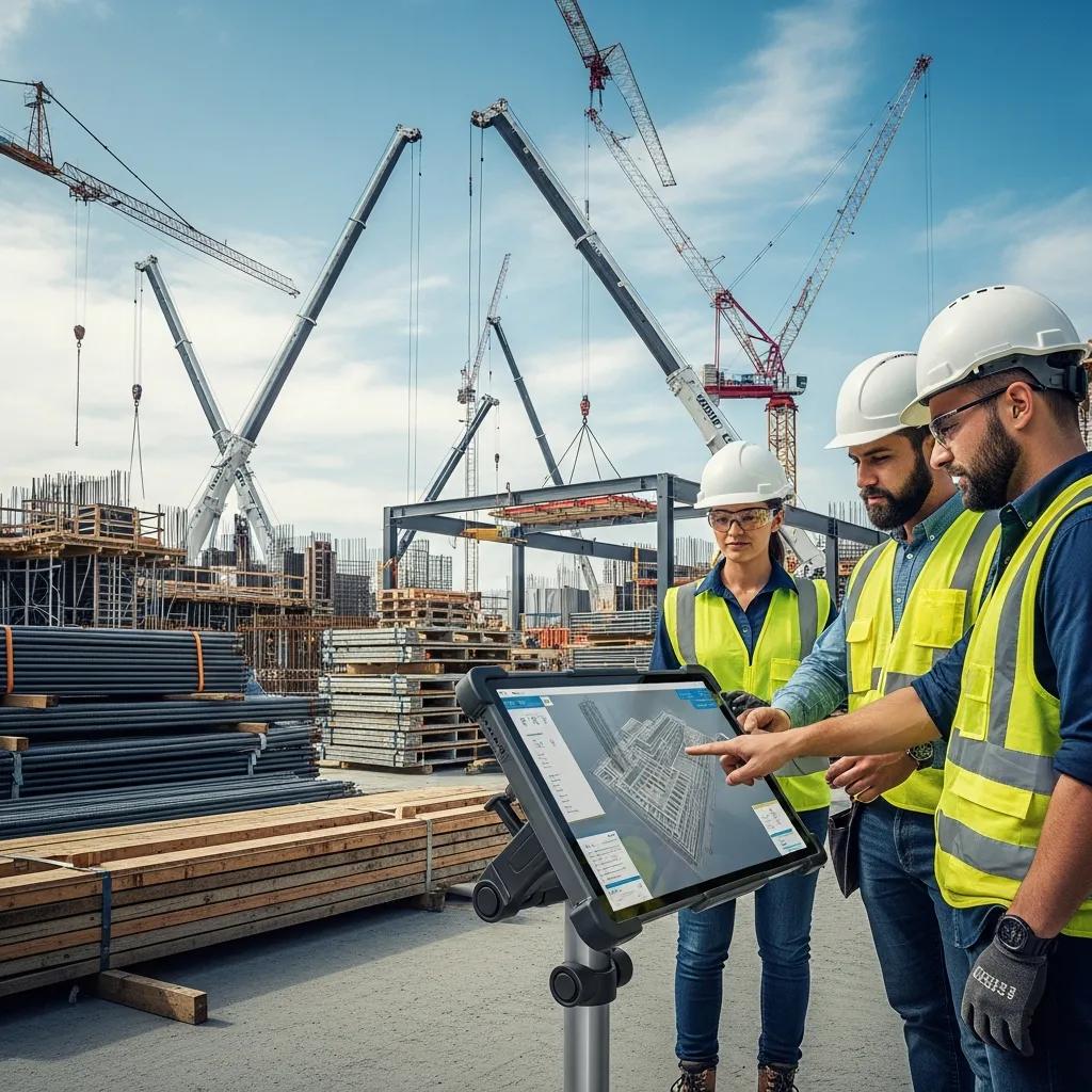
Building Resilient Construction Supply Chains: Practical, Model‑Driven Digital Strategies Supply chain resilience on a construction project is the ability of material, information, and labor flows to absorb shocks, adapt to change, and recover quickly — all while protecting the schedule and budget. Recent swings in logistics, material availability, and labor markets make resilience a top priority for owners and contractors who need predictable outcomes. This guide shows how digital construction workflows — VDC, BIM, 3D scanning, and precision layout — act as early-warning systems, tighten coordination, and cut rework and waste. You’ll get concrete visibility techniques, practical risk-reduction steps, model-driven logistics tactics, supplier collaboration methods, and a look at how AI/IoT and cloud analytics support these efforts. Each section mixes clear technical explanation, short checklists, side-by-side comparisons, and short examples so project teams can map these strategies into procurement, field operations, and coordination with measurable results. How does clearer supply chain visibility make projects more resilient? Supply chain visibility is the near-real-time ability to see where materials are, their condition, and their status across procurement, staging, and installation. Visibility is created by linking data sources — 3D point clouds, BIM objects with tags, and sensor feeds — into a shared model so discrepancies show up early and can be fixed before delays multiply. The main payoff is lower uncertainty: fewer duplicate orders, quicker resolution of mismatches, and smoother handoffs between procurement, logistics, and trades. Better visibility shortens decision cycles, reduces the need for large buffers, and supports just‑in‑time delivery that lowers holding costs. Visibility tools differ in update frequency, accuracy, and integration effort; the table below compares common options and the resilience they deliver. Technology Typical Accuracy Integration Complexity Resilience Benefit 3D Scanning (point cloud) Sub‑centimeter spatial accuracy Medium — requires scan‑to‑BIM workflows Verifies as‑built conditions to prevent mis‑deliveries and staging mistakes IoT Material Tracking (RFID/sensors) Meter‑level to sub‑meter High — requires hardware and network setup Real‑time location and condition alerts reduce loss and damage BIM Integration (procurement linkage) Model‑level component accuracy Low to Medium — depends on data hygiene Traceability from model object to purchase order reduces ambiguity Combining precise as‑built capture with continuous tracking and BIM linkage yields the strongest resilience gains — balancing accuracy and operational practicality. The next section shows how 3D scanning turns visibility into on‑site material verification and staging control. What role does 3D scanning play in live material tracking? 3D scans produce dense point clouds that serve as an objective as‑built record, allowing teams to check quantities, fabricated assemblies, and staged components against the BIM model. The workflow is direct: capture the physical state, align registered point clouds to BIM objects, and run automated comparisons that flag missing or mis‑placed items for procurement or staging teams. This replaces subjective visual checks with measurable verification, cutting disputes over deliveries and preventing install of incorrect parts. For example, scanning a prefabricated MEP rack before mobilization confirms dimensions and connections so parts arrive ready for installation and avoid costly field rework. Those scan outputs then feed into BIM to close the visibility loop and keep procurement and scheduling transparent. How does BIM integration increase supply chain transparency? When BIM objects carry specification and procurement metadata, the model becomes a single source of truth for parts, deliveries, and staging. Linking BIM to purchase orders, ETA fields, and staging locations lets planners trace items from order to installation and makes lead times and sequencing clearer. Operational benefits include fewer last‑minute substitutions, cleaner staging plans for trades, and earlier detection of long‑lead items that threaten the critical path. That linkage also enables automated alerts when a delivered component deviates from modeled parameters so inspection and correction can happen promptly. These visibility capabilities underpin the tactical risk‑management measures that follow — addressing errors, clashes, and supplier interruptions. What practical risk‑management strategies work on construction projects? Effective risk management combines early detection, process controls, supplier tactics, and contingency planning to limit schedule and cost impacts. Core techniques include precision layout to prevent field errors, VDC clash detection to remove design conflicts before procurement, supplier diversification to avoid single‑source failure, and just‑in‑time sequencing to reduce on‑site inventory exposure. Together these tactics lower rework risk, create predictable procurement windows, and preserve schedule buffers for true surprises. Below is a concise mapping of common disruption types and pragmatic mitigations teams can put into practice. Disruption Type Typical Impact Mitigation Approach Material shortages Schedule slips, substitution risk Supplier diversification and early procurement of long‑lead items Design clashes Rework and fabrication changes VDC clash detection cycles and coordinated model sign‑offs Logistical delays Staging congestion and idle labor JIT sequencing and alternative routing plans Field layout errors Rework, wasted materials Precision layout with robotic total station and QA checks Pairing model‑led detection with procurement and supply‑side tactics reduces both the frequency and impact of disruptions. Use this practical checklist as a starting point on every project. Run early VDC coordination cycles to catch and resolve clashes before fabrication. Set precision layout checkpoints to verify critical control points before installation. Identify secondary suppliers for long‑lead items and include contingency terms in contracts. Define JIT delivery windows tied to model‑driven sequences to minimize onsite inventory. The checklist is an operational starting point; the next subsections explain how precision layout and VDC reduce errors and accelerate mitigation. How does precision layout with a Robotic Total Station prevent errors? Robotic Total Stations establish highly accurate control points and automate stake‑out workflows, translating model coordinates to the field with sub‑centimeter repeatability. This reduces human measurement variability through automated staking and verification so installed elements meet design tolerances and connection geometry. The result is less rework from misalignment, preserved procured materials, and protected schedule milestones. For example, precision staking for foundation anchors or MEP penetrations prevents fit issues that would trigger costly fabrication changes and delivery churn. How does VDC enable early clash detection and faster mitigation? Virtual Design and Construction (VDC) centralizes multi‑discipline models and runs scheduled coordination cycles with severity triage so clashes are found and assigned early. The process
Creating Fabrication-Ready BIM Models for Efficiency
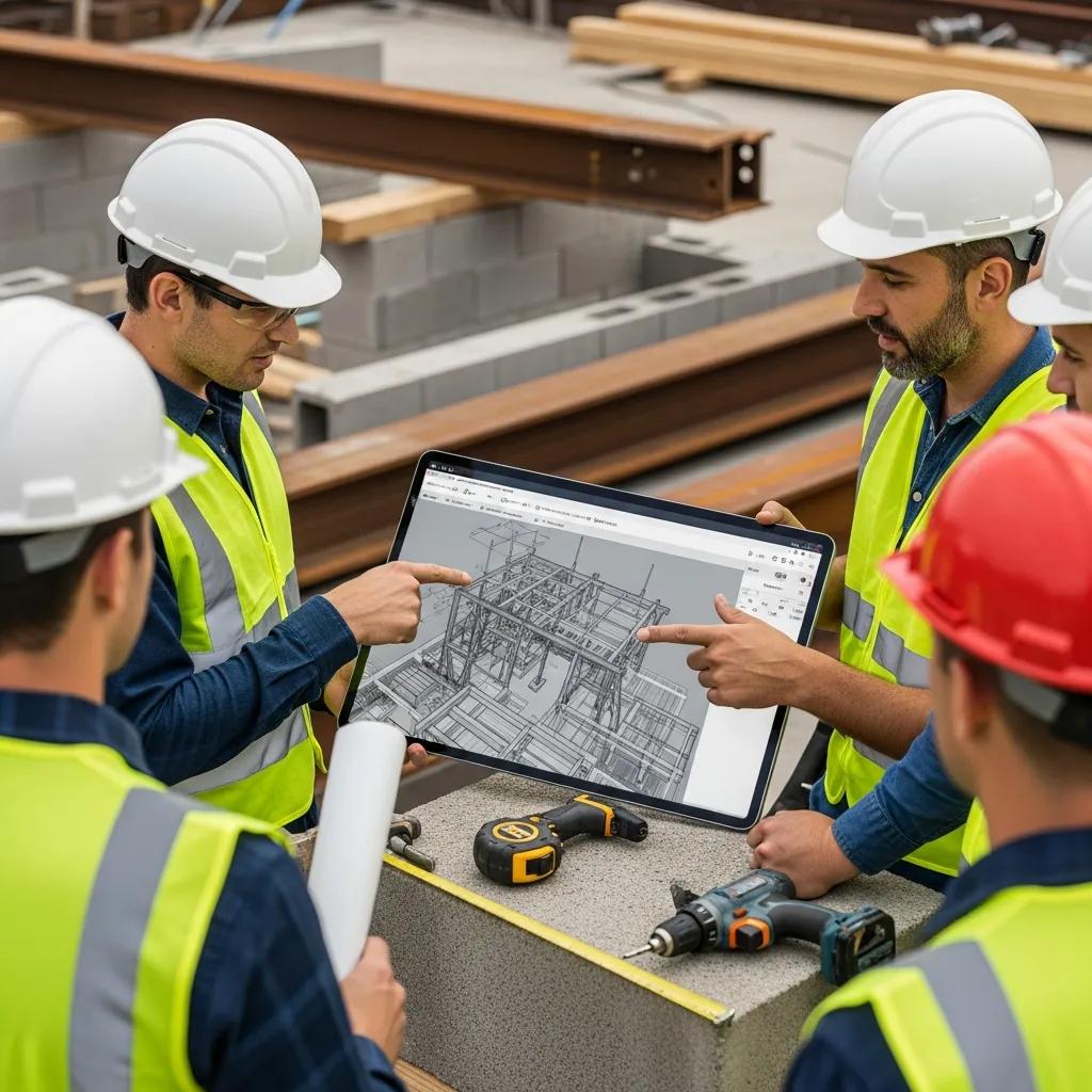
Practical Guide to Fabrication‑Ready BIM: Streamlined BIM Coordination and VDC Integration Fabrication‑ready BIM models are digital, shop‑grade representations of building systems that include precise geometry, fabrication metadata, and clear assembly intent—everything needed to drive shop drawings and offsite manufacturing. By combining LOD 400 geometry, coordinated clash results, and automated shop‑drawing outputs, these models give fabricators and installers unambiguous instructions that reduce rework and compress schedules. This guide walks through how fabrication‑ready BIM, disciplined BIM coordination, and Virtual Design & Construction (VDC) practices work together to deliver measurable efficiencies: fewer RFIs, faster installs, and smarter material use. You’ll find clear LOD expectations, coordination workflows from clash detection through spooling, VDC use cases for sequencing and 4D/5D planning, and the practical technologies that enable precise layout and digital‑twin handoffs. We also explain how Conway Coordination and Layout Services (CCLS) supports fabrication‑ready workflows with specialized modeling, precision layout tools, and VDC consulting—always focused on best practices and measurable ROI. Keywords like fabrication‑ready BIM models, LOD 400 BIM, shop drawing generation, and BIM coordination appear throughout to connect concepts with implementation steps. What fabrication‑ready BIM models are and how they drive construction efficiency A fabrication‑ready BIM model is a federated dataset built to the accuracy and detail required for manufacturing and assembly—typically LOD 400. The efficiency comes from precise geometry paired with fabrication metadata—part numbers, material specs, connection details, and tolerances—so models can be turned into shop packages and CNC inputs without guesswork. The main benefit is less ambiguity for fabricators and installers, which cuts onsite rework, speeds procurement, and shortens lead times for prefabricated assemblies. Knowing exactly what deliverables a fabrication‑ready model must include clarifies handoffs and smooths coordination with manufacturers and suppliers. The table below maps common model elements to their LOD attributes and the deliverables expected by manufacturing or installation teams. This explicit mapping helps teams confirm LOD 400 requirements before production begins. Element LOD Attribute Deliverable MEP Duct Runs Accurate as‑built geometry and connection spools Spool drawings, cut lists, bending schedules Structural Steel Members Fabrication geometry, connection plates, bolt patterns Shop drawings, connection detail sheets, BOM Connection Details Tolerances, welding/bolting information, part numbers Connection detail sheets with material callouts Equipment Mounts Anchor layouts and embed coordinates Mounting plates and anchor bolt schedules That mapping removes interpretation risk for fabricators and installers. When those items exist in the model, RFIs drop and downstream automation for shop drawings and CNC tooling becomes direct. Clear deliverables also improve procurement planning and tighten the connection between design, fabrication, and field installation. What makes a model LOD 400 and fabrication‑ready? LOD 400 models contain fabrication‑specific geometry and the metadata needed for manufacturing—objects represent actual fabricated components rather than conceptual placeholders. That means precise dimensions, splice and connection details, material and finish specs, and part numbers that tie to procurement and shop processes. Fabricators use that information to create spools, bending schedules, and CNC files; without accurate metadata, those outputs require manual work that introduces error and delay. In practice, modelers rely on parametric families with embedded fabrication parameters and standardized naming so automated extraction tools can produce consistent shop sheets. Those attributes feed automated shop‑drawing generation and clash‑detection workflows, preserving prefabrication integrity. Well‑implemented LOD 400 practice makes each model element a single source of truth for both shop and field crews. How fabrication‑ready models improve prefabrication and reduce mistakes Fabrication‑ready models enable clash‑free, dimensionally accurate shop drawings and provide BOMs and spooling instructions that drive fabrication machinery. When geometry and metadata are complete, software pipelines can export schedules, spool maps, and CNC‑compatible files without manual redrafting. That reduces common errors—mis‑measured parts, mismatched connections, incomplete material lists—that often trigger RFIs and rework on site. Validating fit and clearances in the model prevents costly shop rework and late design changes, streamlining logistics and shortening project timelines. Better prefabrication workflows also raise factory QA and smooth site assembly, making modular and offsite manufacturing more predictable and cost‑effective. The result is less waste, fewer delays, and faster commissioning when fabrication matches the model intent. How BIM coordination services streamline fabrication workflows BIM coordination is the repeatable process of federating discipline models, running clash detection, resolving conflicts, and validating model data so handoffs to fabrication are dependable and repeatable. The work involves scheduled federations, prioritized clash reports, coordination meetings, and defined mitigation paths that turn coordination outputs into model updates and RFIs when needed. The core advantage is catching and fixing conflicts early—before fabrication or installation—so change orders and shop rework decline. A consistent coordination cadence creates accountability across trades, improves version control, and keeps the model as the single source of truth for shop drawing generation. Below we map common coordination activities to measurable benefits so teams can prioritize coordination work in preconstruction and design phases. Model Element Coordination Task Benefit/Metric Federated Model Regular clash detection runs Fewer onsite clashes and lower rework rates MEP Systems Clearance verification and routing coordination Less conduit rerouting during install Structural Interfaces Connection checks and tolerance reviews Reduced shop rework on connections Model Handoffs Export of fabrication metadata Faster shop drawing automation and QC These examples show how focused coordination tasks produce quantifiable benefits and let teams measure improvements across fabrication and installation. When model validation includes export‑ready metadata, the handoff to automated shop drawing generation is smoother and more predictable. The coordination workflow typically follows a repeatable loop—clash detection, model update, fabrication handoff—and that repeatability is what scales improvements across projects. A structured coordination process preserves the fidelity of fabrication‑ready models and supports continuous improvement in prefabrication pipelines. What BIM coordination does for clash detection and risk mitigation BIM coordination consolidates discipline models, identifies interferences, and assigns resolution actions that prevent downstream conflicts during fabrication and installation. Clash detection classifies issues—hard clashes, soft clashes, clearance problems—and ranks their severity so teams can triage fixes cost‑effectively. Resolving clashes during design or pre‑fabrication reduces the chance fabricators will build parts that don’t fit, a leading cause of onsite rework and schedule delays. Coordination delivers clash reports, resolution logs, and tracked model revisions that
VDC Construction Consulting in Richmond, VA

VDC Construction Consulting in Richmond, VA: Practical Virtual Design & Construction for Faster, More Accurate Projects Virtual Design and Construction (VDC) consulting brings digital workflows into the field to lower risk, tighten schedules, and increase installation accuracy on Richmond-area projects. This guide walks through what VDC is, why it matters for local permitting and contractor coordination, and how proven practices—centered on BIM, reality capture, and model-driven layout—turn designs into reliable site results. You’ll find the key technologies, step-by-step implementation guidance, industry use cases, and a clear plan to launch a pilot that delivers measurable ROI: less rework, faster turnover, and cleaner handoffs. The content follows the project path from model creation and clash detection through fabrication handoffs and robotic total-station layout, with lists, comparison tables, and workflows to help teams decide next steps for a Richmond pilot. What is VDC Construction Consulting and How Does It Benefit Richmond Projects? VDC construction consulting applies disciplined digital processes—primarily BIM, reality capture, and model-based coordination—to align design, fabrication, and field work and cut uncertainty and rework. The practical chain is straightforward: accurate federated models enable early clash detection and fabrication-ready outputs, which reduce RFIs and limit on-site adjustments during installation. On Richmond projects this typically means smoother permitting reviews, clearer coordination across local trades, and fewer schedule-driven cost premiums. Below we summarize the primary benefits as measurable outcomes, then explain how each one plays out on typical projects. VDC delivers several high-impact, measurable benefits for construction projects in Richmond: Reduced Rework: Regular clash detection and model validation lower on-site corrections and rework percentages. Schedule Compression: Prefabrication and precise layout accelerate installations and shorten critical-path activities. Cost Avoidance: Early coordination curbs last-minute changes and expensive field fixes. Improved Collaboration: Shared federated models and standardized deliverables make communication between designers and trades more efficient. Higher Site Accuracy: Model-driven field layout with robotic total stations yields millimeter-level placement precision. This comparison table links common VDC deliverables to their core benefits and typical impact metrics so teams can estimate ROI before mobilization. VDC deliverables mapped to likely impacts: Deliverable Primary Benefit Typical Impact Clash Detection Reports Reduced onsite conflicts Fewer RFIs and up to 30% lower rework on coordinated systems Fabrication-ready Models Faster prefabrication Shorter lead times and reduced field labor hours Model-based Field Layout Accurate installation Millimeter accuracy; fewer corrective site surveys These deliverables form the practical foundation for ROI: early detection and precise execution convert directly into saved time and cost. With that foundation established, the next section defines VDC and its role across the project lifecycle. Defining Virtual Design and Construction and Its Role in Construction Virtual Design and Construction (VDC) is a process that uses coordinated digital models and repeatable workflows to plan, simulate, and manage construction outcomes before crews start work in the field. VDC centers Building Information Modeling (BIM) as the primary data environment, then pairs it with reality capture and logistics planning to create a single source of truth for project stakeholders. Model-driven coordination surfaces spatial conflicts and constructability issues early, allowing teams to resolve them in preconstruction rather than in the field. In practice, VDC is applied during design development, coordination sprints, prefabrication planning, and model-based field layout—bridging design intent to physical execution. That leads naturally to the practical question: exactly how does VDC lower costs and speed schedules on real projects? How VDC Consulting Reduces Costs and Enhances Project Efficiency VDC consulting reduces cost and boosts efficiency through focused practices like scheduled clash detection, fabrication-ready modeling, and model-based QA/QC for field installation. Clash detection finds geometric and systems conflicts early so trades can coordinate, reducing mid-construction change orders and labor overruns. Fabrication-ready models enable off-site assembly, cutting on-site labor, weather exposure, and quality risks. Model-based QA/QC and field layout—often executed with robotic total stations—translate model coordinates to the site with millimeter precision, minimizing corrective work and disruptive re-sequencing. The section below explains how a firm like CCLS implements these steps for Richmond projects and what a typical engagement looks like. How Does CCLS Implement VDC Consulting Services in Richmond, VA? CCLS delivers VDC consulting through a structured, repeatable process that turns digital models into precise field execution. Our high-level sequence is: onboarding and standards setup, federated model creation, scheduled clash detection and triage, prefabrication/shop-model handoffs, and model-based field layout with verification. Each step produces measurable deliverables and relies on tools such as BIM authoring platforms, 3D laser scanning, point-cloud integration, and Trimble Robotic Total Station layout systems. Below is a concise, numbered process designed to help project teams evaluate a consultant quickly. CCLS follows a clear stepwise implementation for VDC consulting: Project Onboarding & Standards Audit: Review existing models, naming conventions, and deliverable expectations. Model Federation & Coordination: Build federated models, run clash detection, and generate prioritized clash reports. Prefabrication & Shop Model Handoffs: Produce fabrication-ready models and coordinate with trades for off-site builds. Field Layout & Verification: Translate model coordinates to site points with robotic total stations and confirm installations. Training & Support: Deliver on-site and remote training so owners and contractors sustain model-driven workflows. This sequence shows how digital models become actionable field work and sets up the tailored strategies CCLS applies for each Richmond engagement. Tailored VDC Strategy Development and Workflow Optimization Every Richmond engagement starts with a tailored VDC strategy that aligns project goals, stakeholder roles, and deliverable cadence to the client’s risk profile and schedule. We begin with an audit of existing BIM assets and site conditions, then run a pilot coordination sprint to validate standards, clash thresholds, and reporting formats. Deliverables commonly include coordination models, clash matrices with triage notes, fabrication-ready submodels, and handoff procedures that integrate with procurement and prefabrication timelines. CCLS focuses on change management through short training sessions and playbooks that clarify model ownership, issue-tracking protocols, and coordination meeting cadence. A clear onboarding and handover framework helps teams scale the VDC workflow while minimizing disruption to site operations. Technology Integration: BIM, 3D Scanning, and Robotic Total Station Usage At CCLS we integrate BIM authoring, reality capture, and precision
Precise MEP Layout using Robotic Total Station Technology
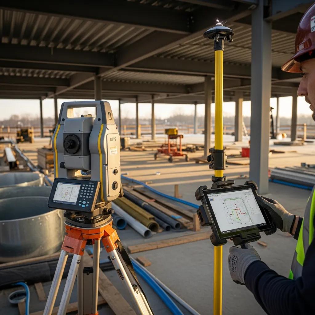
Precise MEP Layout with Robotic Total Stations — Reliable BIM‑to‑Field Execution Accurate mechanical, electrical, and plumbing (MEP) layout drives schedule certainty and cost control. Robotic Total Station (RTS) systems address the tolerance and coordination gaps that most often cause rework. This article shows how RTS—particularly Trimble Robotic Total Station solutions—delivers millimeter‑level accuracy, repeatable stakeout, and direct BIM‑to‑field workflows. You will learn how RTS works, why it outperforms traditional layout methods, how BIM integration and clash detection reduce conflicts, and which MEP tasks gain the most from RTS. We also outline practical implementation steps for HVAC, plumbing, electrical, and anchor‑bolt verification and describe how an experienced provider executes these workflows on real projects. Along the way we include concise lists, comparison tables, and measured project outcomes so teams can evaluate RTS for prefabrication, VDC coordination, and field verification. What is Robotic Total Station Technology and How Does It Enhance MEP Layout? Robotic Total Station technology is an automated surveying instrument that measures angles and distances with optical and electronic sensors, tracks a prism, and stakes BIM‑derived coordinates on site to produce precise construction layout. RTS workflows start by establishing control points, importing model coordinates, and using the robotic instrument to guide a single operator to stake points with millimeter accuracy. The result is fewer layout errors, faster verification, and clearer as‑built records that reconcile back to VDC/BIM. Knowing how the device functions helps explain why RTS replaces many manual layout methods and sets up Trimble‑specific operational details. Conway Coordination and Layout Services (CCLS) deploys Trimble RTS for dedicated MEP layout and verification on complex projects, aligning model coordinates to site benchmarks and cutting rework on critical systems. This example establishes practical credibility while keeping the technical discussion central. How Does Trimble Robotic Total Station Work in Construction Layout? A Trimble Robotic Total Station pairs a precision theodolite with electronic distance measurement and an onboard controller to automate stakeout and data capture. Typical workflow steps include tying control points to site benchmarks, importing BIM or CAD coordinates into the controller, and positioning the RTS to track a prism as the operator moves to each stake point. The controller gives coordinate guidance and records verification logs; automation lets one operator perform tasks that historically required two people. This configuration supports direct model‑to‑field transfers for anchor bolts, hanger points, and equipment setouts, and built‑in calibration routines maintain repeatability across the project. Proper RTS setup requires advance planning of coordinate systems and a robust control network; preparing those elements makes it possible to quantify RTS advantages over traditional methods. What Advantages Does Robotic Total Station Offer Over Traditional Layout Methods? Robotic Total Station outperforms tape, manual transit, and handheld laser techniques by offering higher accuracy, consistent repeatability, and labor savings through automation. Traditional two‑person transit workflows rely on manual alignment and calculations, which create variability and cumulative error risk; RTS mitigates those risks with automated tracking and direct digital coordinate input. Field data typically show 30–50% time savings on stakeout tasks and large reductions in rework when RTS is combined with BIM coordination. The combined effect is shorter layout cycles, fewer on‑site adjustments, and better alignment with prefabrication schedules. Key practical advantages include: Millimeter precision: reduces fit‑up problems in prefabricated assemblies. Single‑operator workflow: lowers labor needs and site congestion. Digital verification: produces auditable as‑built records for QA/QC. These advantages lead directly into quantified benefits across accuracy, time, and cost metrics. What Are the Key Benefits of Using Robotic Total Station for Precise MEP Layout? Robotic Total Station delivers measurable benefits across accuracy, productivity, cost avoidance, and safety while enabling model‑driven prefabrication and better sequencing. By converting BIM coordinates into field control and producing verification logs, RTS prevents common layout mistakes, speeds stakeout, and reduces corrective work that delays schedules. The approach also lowers the number of people required on congested sites, improving safety and reducing coordination overhead. Below we summarize the primary benefits and provide a compact comparison table mapping metrics to typical project values. Robotic Total Station provides four primary benefits: Precision and reduced rework: Millimeter‑level stakeout minimizes misalignment. Productivity: Faster stakeout cycles support concurrent trades and prefabrication. Cost avoidance: Fewer layout errors cut rework expenses. BIM enablement: Direct model‑to‑field workflows streamline clash resolution and sequencing. Introductory table: the table below compares accuracy, time savings, labor model, and typical cost impact for RTS‑based MEP layout. Metric Characteristic Typical Value Accuracy Measurement tolerance for stakeout 1–10 mm Time savings Stakeout and verification cycle reduction 30–50% faster Labor model Operator requirement per layout team Single‑person operation vs. 2+ Cost impact Typical rework avoidance on major MEP conflict Up to tens of thousands of dollars per avoided clash This comparison shows how RTS shifts risk away from unpredictable field rework toward documented, repeatable layout workflows. The next section describes verification practices that make those metrics achievable. How Does Robotic Total Station Ensure Pinpoint Accuracy and Reduce Errors in MEP? RTS delivers pinpoint accuracy through a calibrated control network, instrument self‑checks, and systematic verification reporting that compares field points to model coordinates. The process starts with stable control points tied to the project coordinate system, then uses the RTS to stake points and record as‑built coordinates for each layout location. QA steps include repeat measurements, residual checks against benchmarks, and verification deliverables such as coordinate logs and deviation reports. These practices convert field measurements into auditable data that reconcile with BIM, reducing subjective decisions and many common measurement errors. Consistent verification also supports prefabrication by confirming hanger patterns, sleeves, and anchors match the model before shop fabrication, which speeds installation and reduces site disputes. In What Ways Does Robotic Total Station Improve Productivity and Speed on Site? Robotic Total Station improves productivity by enabling single‑operator workflows, shortening stakeout cycles, and supporting parallel activities like prefabrication and concurrent trade layout. RTS eliminates the need for a second observer and reduces repetitive setups between control points, so crews can stake more points per shift and reassign labor to installation. This speed is particularly valuable for critical‑path MEP activities—duct risers,
Industrial Facility Layout & Coordination in Durham, NC
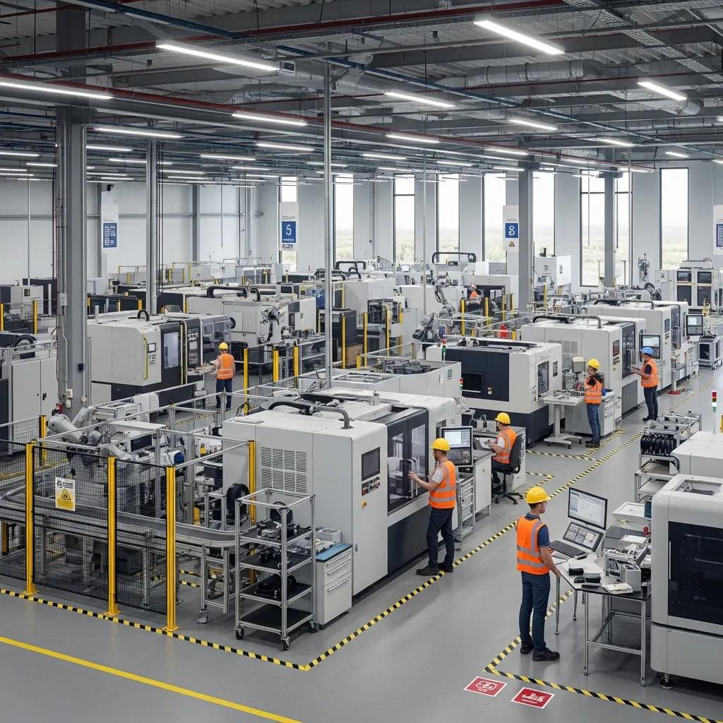
Industrial Facility Layout & Coordination in Durham, NC — Practical, Precision-Driven Solutions for Manufacturing and Construction Industrial facility layout and coordination determine how equipment, systems, and workflows are positioned so plants run safely and efficiently in Durham, NC. This guide shows how precise layout, model-driven coordination, and field-verified as-built documentation cut rework, shorten schedules, and protect operations during new builds and renovations. You’ll get clear explanations of core topics—what facility layout actually involves, how Robotic Total Stations deliver millimeter-level placement, why BIM coordination stops costly clashes, how VDC sequences work to avoid downtime, and how 3D scanning produces dependable as-builts. We focus on practical strategies for Durham’s industries—advanced manufacturing, life sciences, and data center support in Research Triangle Park—offering tool and workflow recommendations plus outcome examples teams can act on to reduce schedule risk and construction cost overruns. What is Industrial Facility Layout and Coordination in Durham, NC? Facility layout and coordination is the process of arranging production equipment, structure, and MEP systems so workflow, safety, and constructability align. It blends spatial planning, sequencing, and model-driven verification to make design intent buildable and to limit clashes and downtime during installation. In Durham projects—where dense MEP routing and heavy machinery share tight footprints—good layout directly supports throughput and regulatory compliance. Below are the primary benefits structured layout and coordination deliver on local projects, helping owners and contractors understand why early investment pays off. Industrial layout and coordination delivers three core benefits for industrial projects in Durham: Increased Operational Efficiency: Smarter material flow, less handling, and intentional equipment spacing boost throughput and shorten cycle times. Improved Safety and Compliance: Proper clearances, planned egress, and correct equipment spacing reduce incident risk and help meet OSHA and NFPA requirements. Cost and Schedule Control: Early clash detection and field-verified layout cut rework, lower change orders, and prevent schedule slippage. Those advantages explain why multidisciplinary coordination is central to plant construction and renovation—and why clearly defined roles and workflows matter on Durham sites. How does facility layout impact industrial efficiency and safety? Layout determines material flow, worker movement, and maintenance access—factors that combine into overall equipment effectiveness (OEE). Poor layouts increase travel distances, create handling bottlenecks, and produce pinch points that slow production and raise safety risks. Well-planned layouts enable lean workflows and predictable maintenance. For example, locating utilities and spare parts near high-use equipment reduces repair downtime and removes the need for risky, rapid movement of heavy loads. Grasping these operational dynamics points directly to the cross-discipline alignment needed to deliver effective layouts in Durham. Who plans and manages industrial layouts in Durham’s manufacturing sector? Layout planning and delivery are a team effort: industrial and process engineers, architects, MEP designers, BIM/VDC coordinators, and general contractors translate operational needs into buildable sequences. Owners and plant engineers set performance and safety requirements, BIM coordinators merge models and run clash cycles, and field surveyors and layout techs validate anchor bolts, equipment positions, and hanger locations during installation. Clear role definitions and continuous coordination reduce ambiguity and speed resolution of constructability issues on Durham projects. Local providers also bridge the gap between model coordination and field execution. Conway Coordination and Layout Services (CCLS) offers Robotic Total Station layout, BIM modeling and coordination, VDC consulting, and 3D scanning to convert coordination outputs into precise field work—especially useful on tight schedules. How Does Robotic Total Station Layout Enhance Industrial Projects in Durham? Robotic Total Station layout is a survey-driven, automated positioning workflow that places points in the field with millimeter-level precision by tracking a prism or reflector against a digital model. The technology improves repeatability, reduces manual measurement error, and enables direct field-to-model verification for MEP hangers, anchor bolts, and equipment set points. Robotic Total Stations integrate with BIM and VDC to export coordinate sets for installation and to import as-built verification data back into models. Below is a practical comparison of common layout tasks showing expected accuracy and typical deliverables for industrial work. The following table compares common layout tasks, expected accuracy, and typical deliverables for Robotic Total Station-driven workflows. Task Typical Accuracy Common Deliverable MEP hanger layout ±5–10 mm Field layout points, hanger position list Anchor bolt verification ±2–5 mm Anchor as-built report, coordinates CSV Equipment/foundation layout ±3–10 mm Anchor bolt layout, equipment set points This snapshot shows Robotic Total Stations deliver consistent precision across tasks, and that coordinate exports, CSVs, and verification reports feed directly into model reconciliation and quality control workflows. What are the key advantages of using Trimble Robotic Total Station for industrial layouts? Trimble Robotic Total Stations offer four core benefits: high accuracy, faster layout cycles, consistent repeatability between crews, and clean integration with model coordinates. Millimeter-level accuracy reduces field rework and inspection time; robotic tracking speeds multi-point layouts that would otherwise take many labor hours; and repeatability lets following trades rely on prior layout without redundant checks. Those benefits are especially valuable on Durham projects with dense MEP and tight equipment tolerances. How is robotic total station technology applied in MEP and structural coordination? Typical robotic layout moves from model export to stakeout to verification and reconciliation: BIM exports coordinates for hangers, penetrations, and anchors; field crews stake the points and install components to those coordinates; then as-built coordinates are captured and compared to the model for clash checks. This closed-loop process catches spatial conflicts before they become costly field changes and supports anchor bolt verification and penetration coordination. VDC ties into this workflow through scheduled layout windows and prefabrication alignment to improve on-site assembly and constructability. After reviewing workflow applications, teams often compare tasks to decide which benefit most from robotic layout versus conventional methods—an evaluation that naturally transitions into BIM-driven coordination where layout and clash data converge. Why is BIM Coordination Essential for Manufacturing Plant Layouts in Durham? BIM coordination brings discipline models together to detect clashes, sequence installations, and produce deliverables that cut on-site errors and rework. By identifying spatial conflicts virtually—between MEP, structure, architecture, and equipment—teams resolve issues before crews mobilize, improving predictability for plant construction. Coordination produces clash
Anchor Bolt Verification Services in Greenville, SC
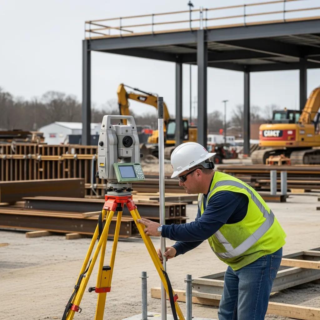
Anchor Bolt Verification in Greenville, SC — Precision Layout for Reliable Structures Anchor bolt verification confirms installed anchors match the engineered locations, orientations, and elevations so structural connections fit and assemblies perform as intended. That verification prevents costly rework and erection delays, keeps projects code-compliant, and preserves structural integrity. In this guide we explain why verification matters for Greenville projects, how a disciplined field workflow operates, which technologies improve accuracy, who benefits most, and how QA and compliance are documented. We also show practical examples using tools like robotic total stations, BIM coordination, and 3D scanning, and outline what project teams should provide to speed scheduling and technical review. Why Anchor Bolt Verification Matters on Greenville Projects Anchor bolt verification is the on-site check that anchors meet engineered coordinates, tolerances, and orientation so they can transfer loads and fit connections correctly. Accurate verification reduces structural risk, limits rework, and protects the schedule by catching deviations before steel erection or equipment installation. On Greenville jobs, early verification prevents situations where base plates cannot be shimmed or fabricated connections must be altered—scenarios that create downtime and extra fabrication. The section below explains how placement accuracy affects stability and load paths. Anchor bolt verification delivers three core benefits for Greenville projects: Safety assurance: Verifies anchors will transfer loads as designed and helps prevent connection failures. Cost avoidance: Finds deviations early to avoid rework, fabrication changes, and schedule impacts. Compliance: Produces the documentation owners and inspectors require for acceptance and special inspections. These advantages show why pre-pour and pre-erection verification are built into disciplined layout workflows and lead to more predictable outcomes. How Accurate Anchor Bolt Placement Affects Structural Stability Anchor placement controls load paths, connection fit-up, and the ability of base plates and anchors to carry shear and tension as designed. When bolts are placed within millimeter-level tolerances relative to base plates, connections align, grout and weld interfaces perform, and members resist applied forces according to the engineer’s assumptions. Tight-tolerance projects—industrial or healthcare—often require only a few millimeters of deviation; larger structural elements may accept somewhat broader ranges set by the engineer of record. Knowing those thresholds helps teams set verification frequency and plan remedial work when needed. Risks and Costs of Misaligned Anchor Bolts Misplaced anchor bolts trigger direct costs—fabrication rework, extra labor, or anchor replacement—and indirect costs such as schedule extensions, crane downtime, and contractual disputes. Rework frequently consumes a disproportionate share of unexpected project expenses and can ripple into erection sequencing and equipment installation. Safety also suffers when connections are forced to fit or field-built shims exceed approved limits, potentially undermining design assumptions. The list below summarizes common impacts to help teams evaluate remediation options. Fabrication changes: Reworking prefabricated members to match field conditions adds time and cost. Schedule delays: Erection and following trades stall when anchors are out of tolerance. Increased risk: Improvised fixes can introduce safety and performance problems. Because of these consequences, precise, early verification is a core risk-management practice on complex projects. Our Anchor Bolt Verification Process at CCLS Our process ties digital plan intake to precise field layout with a Trimble Robotic Total Station (RTS) and to clear as-built documentation that confirms compliance with engineered coordinates and tolerances. Conway Coordination and Layout Services (CCLS), a family-owned firm serving the Southeast, begins with BIM/CAD import and datum checks, moves to RTS-based layout and measurement, and finishes with deviation reporting and remediation coordination. This structured workflow reduces coordinate-conversion errors, aligns field crews and fabricators, and produces traceable records for special inspections. The paragraphs below describe key steps, expected tolerances, and how deliverables support contractor and engineer decisions. The table below summarizes verification phases, typical tolerances, and the deliverables stakeholders receive. Verification Phase Typical Tolerance Deliverable Digital Plan Integration ±2–5 mm (model-to-control) Validated model references and coordinate report RTS Field Layout ±1–3 mm (final set positions) Field coordinate logs and stakeout confirmation As-Built Documentation ±2–5 mm (measured vs. designed) Deviation table, annotated drawings, photos This table sets expectations for precision at each stage and identifies the practical outputs teams use to accept or remediate work. The following section explains how digital plan integration reduces errors before crews mobilize. How Digital Plan Integration Improves Accuracy Digital plan integration creates a single source of truth by importing BIM or CAD models into the layout control environment and ensuring coordinates, datums, and model geometry align with site control. Early verification of the coordinate system and datum prevents unit or reference mismatches that produce systematic offsets in anchor locations. Integration also supports clash detection and early communication with fabricators when embeds conflict with other trades, reducing surprises during erection. Use this checklist before mobilizing: confirm the coordinate system, verify control monuments, and run a model-to-field spot check. Checklist: Confirm coordinate system, verify control monuments, perform model-to-field spot checks. These pre-field checks set the RTS workflow up for success and reduce repeat site visits. Using a Trimble Robotic Total Station for Precise Layout A Trimble Robotic Total Station delivers millimeter-level accuracy and automated stakeout, enabling teams to place anchors and record as-built coordinates efficiently. RTS setup begins by establishing control points tied to the project datum, then uses robotic positioning to stake target anchor locations from the integrated model. Each measured anchor position and orientation is logged, producing a verifiable dataset to compare against the design model and to generate deviation reports and annotated as-built drawings. RTS reduces human error compared with tape-and-transit methods and provides the traceable records engineers need for acceptance. Data recorded by the RTS feeds reporting workflows that document variances and recommend remediation, preparing the team for acceptance or corrective action. How Advanced Technology Improves Verification Advanced tools—Trimble RTS, BIM/VDC coordination, and 3D scanning—tighten tolerances, speed data exchange, and enable model-to-field comparisons that catch errors earlier. RTS provides precise layout and measurement, BIM/VDC supports coordination and clash resolution, and 3D scanning captures dense as-built data for deviation analysis. When combined (BIM → RTS → 3D scan) these technologies reduce RFIs, accelerate erection, and produce defensible QA/QC records for
Digital Twins: Revolutionizing Building Project Management

Digital Twin Construction Project Management: Real‑Time Control for Smarter Building Delivery Digital twins in construction are live, synchronized digital replicas of a building or infrastructure project. By merging BIM models, 3D point clouds and real‑time field feeds, a twin lets teams see as‑built conditions, verify design intent, and base decisions on the latest site information — improving coordination and cutting costly rework. In this article you’ll get a clear definition of a construction digital twin, learn how it differs from BIM and VDC, and follow the practical workflows that make twins usable — from 3D scanning and point‑cloud processing to BIM integration and continuous monitoring. We cover benefits across design, construction, commissioning and operations, and explain how VDC consulting and verification methods preserve twin fidelity on the jobsite. Finally, we show how Conway Coordination and Layout Services (CCLS) combines scanning, BIM, VDC and robotic layout to deliver validated digital twins. By the end, you’ll understand the technology, workflows and measurable value a digital twin brings to modern project management. What is a Digital Twin in Construction and How Does It Transform Project Management? A construction digital twin is a dynamic, data‑driven model that mirrors the physical building by linking BIM geometry, 3D point‑cloud captures and live sensor or field inputs into a continuously updated representation. Its power comes from joining static design information with live feeds — sensors, verification scans and progress capture — so stakeholders are viewing current conditions instead of outdated plans. Continuous synchronization lowers uncertainty in execution, shortens feedback loops and improves decision‑making for everyone from owners to trade contractors. Teams move from reacting to problems to proactively preventing them, which reduces delays and cost overruns. The next section contrasts digital twins with BIM and VDC to clarify how each contributes value. How Does Digital Twin Technology Differ from BIM and VDC? BIM, VDC and digital twins are tightly related but serve distinct functions: BIM is the structured model of design data; VDC is the delivery approach that applies models to planning and construction workflows; and the digital twin adds a live‑data layer that keeps the model in sync with reality. BIM is the authoritative source for geometry and attributes, VDC organizes coordination, sequencing and simulation, and the digital twin ingests point clouds, IoT telemetry, schedule updates and field verification to create a living model for analytics and operations. Practically, a design clash is identified in BIM coordination, resolved through VDC workflows, and then validated against the digital twin during construction — illustrating how model, process and live data work together to produce predictable outcomes. What Are the Key Benefits of Digital Twins for Construction Projects? Digital twins produce measurable gains across cost, schedule, quality and risk by delivering a single source of truth that’s continuously validated against the site. Live reconciliation of model and field reduces uncertainty and speeds coordination and change management. For owners and delivery teams, the primary gains are fewer clashes and rework, improved schedule predictability and stronger operational readiness at turnover. Digital twins provide distinct project benefits: Reduced Rework and Clashes: Real‑time model‑to‑site comparisons cut avoidable scope changes and RFI cycles. Improved Schedule Confidence: Up‑to‑date progress data enables better sequencing and reduces float loss. Enhanced Quality and Commissioning: High as‑built fidelity supports faster, more accurate commissioning and fewer punch‑list items. To quantify these advantages, the table below summarizes typical impacts and representative values teams can expect when digital twins are used effectively. Different digital twin benefits map to measurable project impacts. Benefit Area Metric Representative Impact Cost Impact Change‑order and rework reduction 5–15% potential cost avoidance Schedule Impact Reduction in schedule delays 10–20% fewer critical‑path delays Risk Reduction Fewer RFIs and coordination issues 20–40% decrease in coordination cycles How Does CCLS Create and Integrate Digital Twins Using BIM and 3D Scanning? Building a reliable digital twin starts with precise reality capture, disciplined processing and careful BIM integration — each step ensuring the twin accurately represents the built environment with usable metadata. Typical workflow flows from 3D laser scanning to point‑cloud registration, model reconciliation and metadata enrichment, with QA checkpoints to confirm alignment. That process produces registered point clouds, as‑built BIM models and integrated datasets ready for analytics and handover. The sections below explain scanning’s role, how BIM becomes the twin’s backbone, and how services map to lifecycle deliverables. What Role Does 3D Scanning and Point Cloud Data Play in Digital Twin Creation? 3D laser scanning captures dense point clouds that reflect the exact geometry of existing conditions and newly constructed elements — essential for accurate as‑built records and validation. Scans are registered and geo‑referenced to create a single coordinated dataset that underpins model reconciliation and clash analysis, cutting dependence on manual measurements. Processing point clouds yields meshes or surfaces modelers reference when building or updating BIM elements, so the twin starts with high spatial fidelity. This reality‑capture foundation reduces downstream surprises, speeds coordination and supports precise verification during layout and commissioning. How Is BIM Integrated to Form the Foundation of a Dynamic Digital Twin? BIM integration turns point‑cloud geometry into intelligent model elements and enriches those elements with metadata — asset attributes, maintenance schedules and performance baselines — that enable operations use cases. Modelers reconcile geometry to standards, tag assets for facility systems and prepare data schemas so the model can ingest live feeds from sensors and project systems. Once asset‑rich and referenced to the point cloud, BIM becomes the structural layer of the digital twin and the platform for analytics, simulations and handover to operations. This preparation ensures the twin supports lifecycle activities from construction verification through long‑term facility management. Different services map to digital twin lifecycle stages and deliverables below. Service Role in Digital Twin Lifecycle Deliverable / Outcome 3D Scanning Reality capture for as‑built fidelity Registered point cloud datasets 3D Point Cloud Rendering & Model Integration Point‑cloud processing and alignment Surface models and model reconciliation BIM Modeling and Coordination Semantic modeling and asset tagging Asset‑ready BIM with metadata VDC Consulting & Construction Services Workflow integration and validation Coordinated
Improving Construction Project Efficiency in Orlando, FL
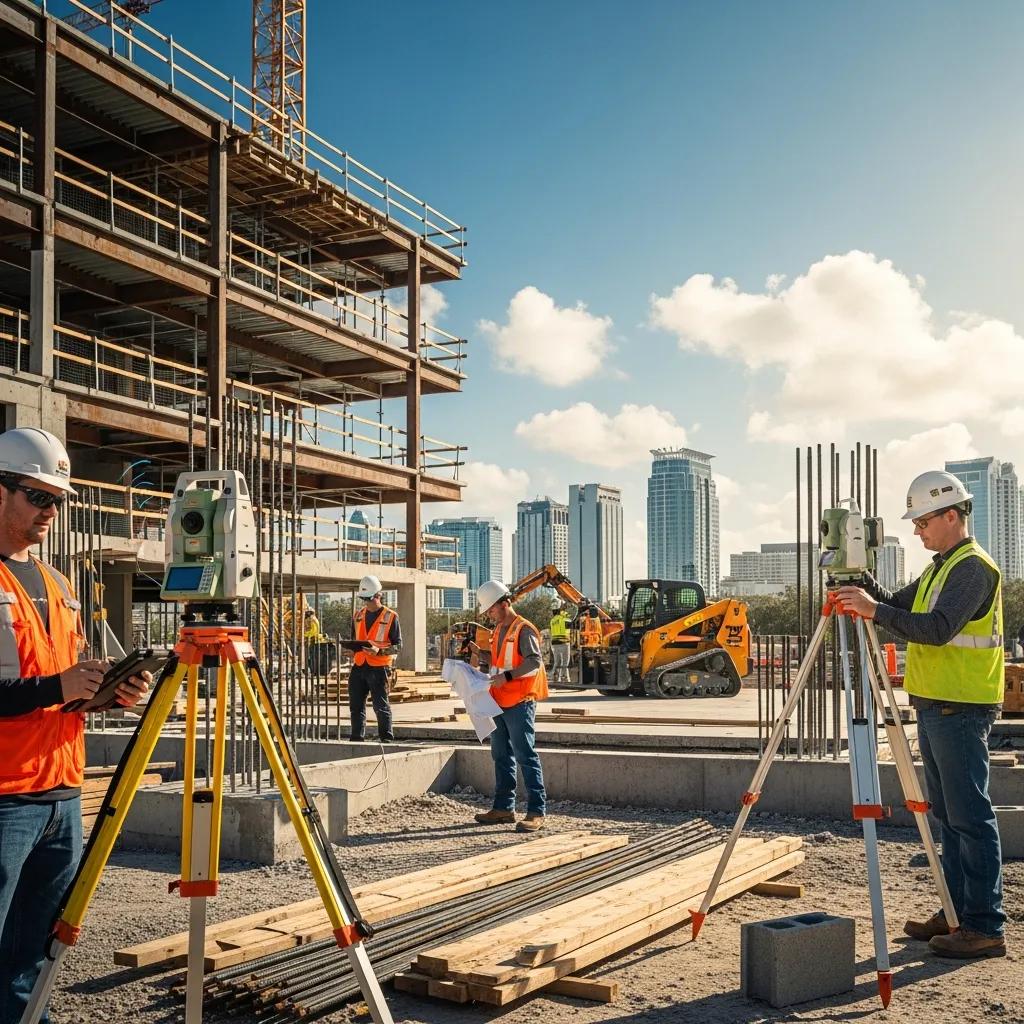
Improving Construction Project Efficiency in Orlando, FL — Practical Technologies and Proven Workflows Construction efficiency in Orlando means finishing work on time, on budget, and with minimal rework — the things that protect margins and keep clients satisfied. This guide breaks down the biggest drivers of inefficiency on local projects — rework, coordination gaps, and inaccurate field layout — and shows how proven technologies like Robotic Total Station layout, Virtual Design and Construction (VDC), BIM coordination, and 3D scanning lower risk and improve schedule compliance. You’ll see how millimeter‑level layout, model‑driven coordination, and data‑led planning cut RFIs, reduce rework, and tighten sequencing on Florida jobs. The guide connects typical regional challenges to concrete tools and workflows, compares them to conventional methods, and explains how integrated services are deployed on site. Read on to understand which interventions deliver the largest schedule and cost improvements and how to prioritize them during preconstruction and early field work. What Are the Key Challenges Affecting Construction Project Efficiency in Orlando? Orlando projects combine common industry pain points with regional pressures that increase schedule risk and rework. Rework can quickly consume budgeted labor and materials, and on active sites it cascades into overtime, duplicated handling, and lost productivity. Local permitting timelines, complex trade coordination among multiple subcontractors, and weather‑driven sequencing disruptions add friction and tighten margins on commercial and institutional projects. Below are the primary challenges and why they matter for teams working in central Florida. Rework and field corrections: Issues found after installation require demolition and replacement, increasing material waste and labor hours. Poor trade coordination: MEP clashes and sequencing gaps force trades to wait or redo completed work, delaying critical activities. Inaccurate field layout: Conventional layout methods allow tolerance drift that becomes costly to correct during finishing stages. Permitting and external delays: Administrative holds and inspection timing can disrupt planned sequences and resource allocation. These factors interact: layout errors create clashes, clashes multiply rework, and permitting delays shave schedule float — making every rework event more expensive. Mapping that causal chain helps teams select targeted interventions that prevent downstream impacts and keep projects on schedule. How Does Rework Impact Project Budgets and Timelines? Rework raises direct costs through extra labor and replacement materials and creates indirect costs from schedule disruption and reduced productivity. Fixing a misplaced anchor bolt, resolving an MEP clash, or correcting an incorrect embed often requires demolition, re‑ordering or re‑fabrication, and re‑sequencing trades — all of which lengthen the critical path. The knock‑on effects increase site congestion, raise safety exposure during remedial work, and frequently trigger overtime or expedited shipping to recover schedule, amplifying budget risk. Early detection through model coordination and precision layout limits rework by catching conflicts before installation, preserving float and protecting contingency. Understanding how detection leads to correction clarifies why investing in prevention — better layout, clash detection, and field validation — yields outsized returns on both schedule and cost. Avoiding a single major rework event can prevent multiple downstream delays that would otherwise cascade across subcontractors and inspections, safeguarding contractual milestones and owner expectations. What Common Causes Lead to Delays and Inefficiencies in Florida Construction? Delays and inefficiencies come from both technical gaps and external pressures that are especially relevant in Florida. Incomplete design details create coordination gaps because models lack the specificity installers need, prompting RFIs and late changes. MEP routing conflicts, improper clearances, and prefabrication mismatches are frequent sources of on‑site rework. Conventional surveying and layout methods generate cumulative tolerance drift that affects finishes and connections. External issues — permitting timelines, long material lead times, and weather interruptions — compress schedule buffers and increase the cost of corrective actions. Mitigations should match the cause: robust BIM coordination closes design gaps, precision layout eliminates tolerance accumulation, prefabrication shifts work off site, and data‑driven planning accounts for inspection and permit windows. Prioritizing these steps in preconstruction reduces the chance that site‑level problems force costly schedule recovery later. How Does Robotic Total Station Layout Enhance Precision and Reduce Errors? Robotic Total Station layout uses an automated, model‑linked instrument to place points with millimeter‑level accuracy, improving installation fidelity and cutting layout‑related rework. The instrument locks to a prism or reflector and ties directly to BIM coordinates, enabling single‑operator workflows that transfer digital design data to the field with high repeatability. That reduces field adjustments, improves fit‑up for structural and MEP elements, and speeds verification of critical points like anchors and embeds. Below are the operational benefits that explain why teams deploy robotic layout for tight‑tolerance work. Millimeter accuracy: Precision required for anchor bolts, prefabricated assemblies, and tight MEP clearances. Single‑operator efficiency: Fewer personnel and less time spent moving instruments and re‑checking points. Direct model integration: BIM coordinates go straight to the site, cutting transcription errors. Those advantages translate to measurable productivity gains and lower schedule risk: fewer corrective tasks during installation mean crews work planned sequences instead of reacting to layout mistakes. What Are the Benefits of Millimeter-Level Accuracy in Orlando Construction Projects? Millimeter‑level accuracy produces clear downstream value for work with tight tolerances — MEP rough‑ins, structural anchor placement, and prefabricated modules. When layout points match design coordinates, prefabricated components fit without field rework, reducing delays to adjacent trades. Correct anchors and embeds cut punch‑list items and shorten commissioning windows because systems align as modeled. Higher installation fidelity also lowers site disruption from multiple trades re‑entering an area to fix earlier errors. Getting critical geometry right at the start supports faster turnover, better client satisfaction, and fewer schedule extensions caused by corrective tasks that consume critical‑path resources. How Does Robotic Total Station Technology Compare to Traditional Layout Methods? Robotic Total Station technology surpasses tape‑and‑transit or manual staking in accuracy, speed, and digital interoperability, making it ideal for complex commercial work. Traditional methods often require several crew members, manual coordinate conversions, and repetitive checks — increasing transcription errors and tolerance drift. Robotic systems accept digital model inputs, perform remote measurements, and let a single operator re‑establish points quickly, reducing setup time and misinterpretation of design data. Beyond
Key Emerging Technologies Shaping the Construction Industry

Key Emerging Technologies Shaping the Construction Industry — Trends & Innovations for 2025 Construction is at an inflection point: digital platforms, robotics, and high-fidelity reality capture are coming together to tackle persistent issues like schedule risk, quality gaps, and fractured collaboration. This article outlines the leading construction technologies for 2025, explains why they matter, and shows how teams turn them into measurable results—less rework, faster turnover, and safer jobsites. You’ll find clear definitions, how each technology works in practice, and real examples for VDC/BIM integration, robotic layout, 3D scanning and digital twins, plus the combined effects of AI, AR/VR, and IoT on delivery. The focus is practical: model-driven workflows that connect design to field execution, instruments that push layout accuracy to millimeter tolerances, and data streams that improve decisions. Each section includes actionable lists, comparison tables, and short case notes so project teams can evaluate adoption strategies and vendors. Mentions of Conway Coordination and Layout Services (CCLS) appear only when they help illustrate real-world application—this is a topic-first guide to support better decision-making on your projects. What Are the Top Construction Technology Trends in 2025? In 2025, construction tech clusters around digitization, automation, and enhanced insight. VDC and BIM keep driving model-led execution; robotics and automated layout boost field precision; 3D scanning and digital twins close the loop between as-built conditions and design intent; and AI, AR/VR, and IoT turn data into planning, safety, and monitoring tools. Each trend responds to common pressures—labor shortages, schedule demands, and sustainability targets—and delivers tangible benefits such as fewer RFIs, shortened delivery windows, and lower lifecycle costs. Industry studies show projects using integrated digital workflows report measurable drops in rework and schedule variance, which explains why these technologies are converging on today’s jobsites. Recognizing these trends helps teams prioritize investments that yield the strongest returns in coordination and field execution. Top construction technology trends for 2025 with concise definitions and primary benefits: VDC / BIM: Model-driven coordination across disciplines to reduce clashes and rework. Robotics & Automated Layout: Mechanized field tools that speed layout and improve placement accuracy. 3D Scanning & Point Cloud Workflows: Reality capture producing as-built datasets for verification and modeling. Digital Twin: Operational replicas that combine BIM and sensor data to support commissioning and FM. AI & Predictive Analytics: Data-driven forecasting that optimizes schedules, procurement, and risk mitigation. AR/VR Visualization: Immersive review and training tools that improve comprehension and safety. IoT & Connected Jobsite: Sensor networks for equipment monitoring, environmental tracking, and material control. Drones & Photogrammetry: Aerial capture that speeds surveying and progress documentation. These trends set up deeper operational shifts in coordination and layout—next we look at how digital transformation drives efficiency on projects. How Is Digital Transformation Driving Construction Efficiency? Digital transformation in construction means linking design models, project data, and field work into one collaborative workflow that cuts manual handoffs and information loss. Tools like cloud model repositories, automated clash detection, and mobile model viewers let teams resolve issues in the office before they become costly field problems. The payoffs are measurable: fewer RFIs, lower change-order rates, and better schedule adherence when everyone uses consistent, model-driven processes. For example, a mid-size hospital project used integrated 4D sequencing to reduce schedule variance by smoothing handoffs between specialty trades and the GC—reducing site congestion and shortening critical-path activities. Understanding these mechanisms points to the specific tools and management practices that improve project-level performance. Which Technologies Are Revolutionizing Project Management? Project management tools now mix predictive analytics, model-based scheduling (4D/5D), and collaborative platforms that centralize data for clearer decisions. AI-driven schedulers analyze historical performance and real-time progress to flag high-risk activities before delays compound, while 4D sequencing ties model geometry to time to reveal phasing conflicts. Cloud collaboration platforms become a single source of truth for drawings, models, RFIs, and submittals—speeding approvals and clarifying accountability across trades. The typical outcome: earlier detection of sequencing issues and more accurate forecasts for resource needs, which reduces float erosion and unplanned overtime. Together these capabilities form the operational backbone of modern VDC and coordination strategies and directly inform layout and field verification workflows. How Does Virtual Design and Construction Enhance Modern Building Projects? Virtual Design and Construction (VDC) is the disciplined use of BIM, coordination processes, and simulation tools to manage delivery from design through turnover. VDC translates multi-discipline models into coordinated construction plans, using clash detection and sequencing to cut field conflicts and optimize work packages. The result: fewer surprises, more predictable schedules, and tighter budget control through early identification of constructability issues. A typical VDC roadmap—assessment, model federation, clash cycles, and model-to-field integration—aligns stakeholders around shared data and creates the conditions for reliable model-driven workflows that reduce rework across the project lifecycle. VDC components compared by what they deliver and why they matter: Component Role in VDC Value Delivered Federated BIM Model Combines architectural, structural, and MEP models Enables cross-discipline clash detection and coordinated planning Clash Detection Automated conflict identification Reduces on-site rework and change orders 4D/5D Scheduling Links model geometry to time and cost Improves sequencing, cost forecasting, and procurement timing Mobile Model Access Field access to latest models Ensures accurate layout and verification at point-of-work This comparison shows how each VDC element contributes to coordinated execution and smoother turnover—next we cover what VDC consulting actually delivers. VDC consulting defines strategy, model governance, and on-site integration to standardize processes across teams. Consultants set up clash-detection workflows and resolve coordination issues before field work begins. Consultants train project staff on model-based methods and support deployment of field tech for model-to-field layout. Consultants track KPIs—like RFI volume and change-order exposure—to quantify VDC’s project impact. VDC consulting produces measurable results: streamlined coordination, fewer RFIs, and reduced schedule risk that lower total project costs. For teams exploring adoption, pairing a VDC strategy with robust field tools helps ensure model fidelity reaches the jobsite. Conway Coordination and Layout Services (CCLS) provides VDC consulting that includes custom strategy development, technology implementation and training for BIM and clash detection, plus on-site or remote VDC support. CCLS
Streamlining Renovation Projects with 3D Scanning
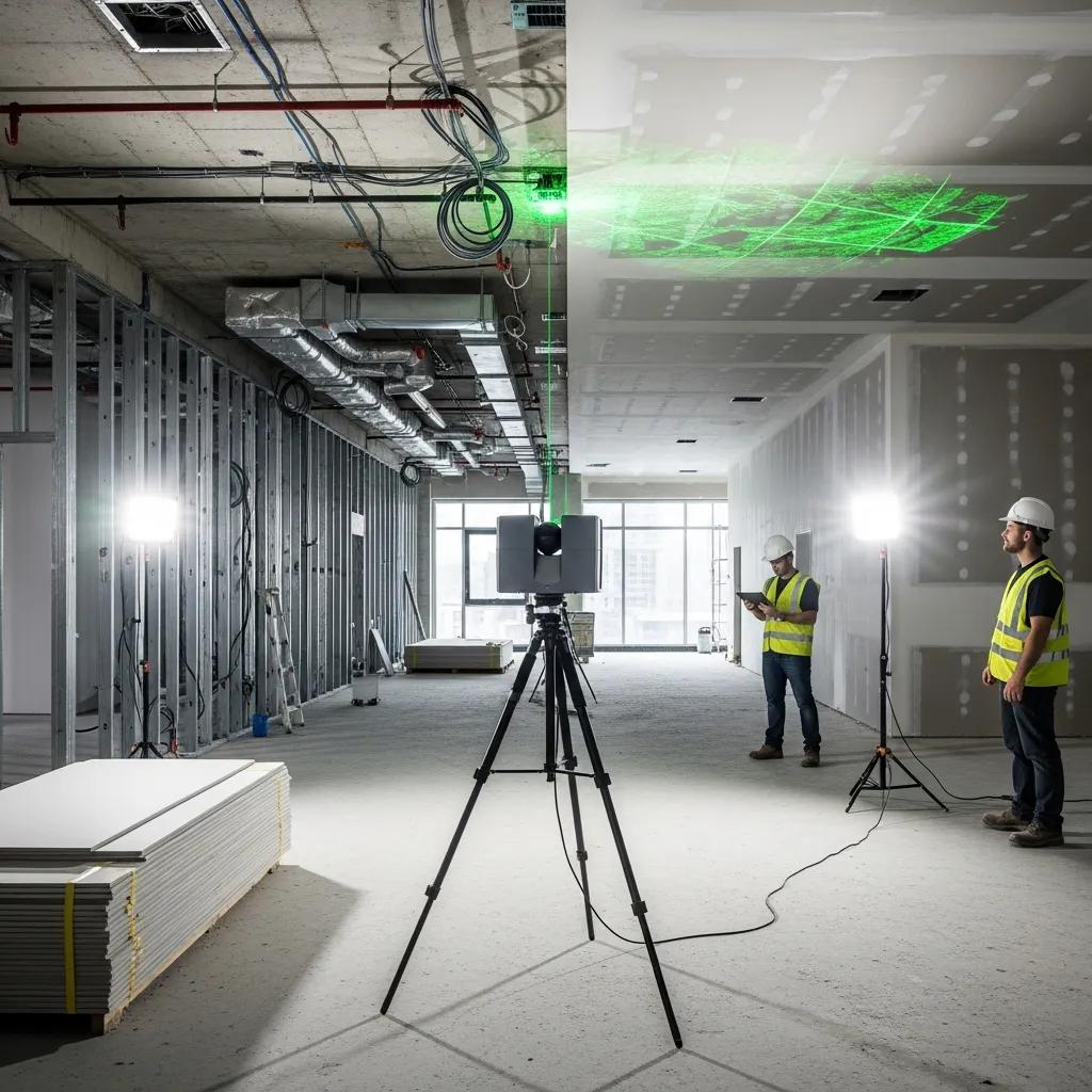
Streamlining Renovation Projects with 3D Scanning for Accurate As‑Built Documentation and Faster Construction Successful renovations start with a reliable picture of the existing conditions. 3D scanning delivers high‑fidelity as‑built documentation that reduces uncertainty and speeds decisions. This guide walks through reality capture—3D laser scanning and LiDAR—explaining how point cloud data powers scan‑to‑BIM, clash detection, and Virtual Design & Construction (VDC) coordination to simplify renovation workflows. You’ll get practical steps for turning scans into usable BIM models, examples for retrofits and historic preservation where non‑invasive surveys matter, and clear metrics for cost and schedule advantages. We also note where to involve specialized providers for targeted Scan to BIM and model coordination. Keywords such as renovation scanning, scan to BIM, point cloud data, and clash detection in renovations are used to keep this resource discoverable and immediately usable. How 3D Scanning Improves Efficiency and Accuracy on Renovation Projects 3D scanning captures dense, georeferenced point clouds that reflect existing conditions at near‑millimeter fidelity. That verified baseline lets teams check assumptions before demolition or retrofit begins, cutting measurement errors and enabling remote dimension verification. Designers, contractors, and owners use the same digital reference to shorten RFIs and speed procurement. When point clouds feed coordination workflows, MEP, structural, and architectural teams find clashes earlier and plan work with fewer surprises. The list below summarizes the primary efficiency gains and shows how Scan to BIM and VDC build on captured data. Direct benefits of 3D scanning for renovation projects include: Reduced measurement errors: Point clouds replace tapes and hand sketches for critical dimensions and clearances. Faster verification: Remote review of scanned areas reduces site visits and accelerates approvals. Improved coordination: Accurate geometry enables earlier clash detection and less on‑site rework. Smarter procurement: Verified measurements improve material takeoffs and cut overordering. These improvements translate to fewer change orders and cleaner handoffs to construction teams — which naturally leads into how the scanning technology works on renovation projects. What Is 3D Laser Scanning and How Does It Help Renovations? 3D laser scanning—a type of terrestrial LiDAR or reality capture—uses rotating lasers and high‑resolution sensors to sample surfaces and create dense point clouds that represent building geometry. Scanners collect millions of points with color and intensity values, capturing walls, MEP runs, structure, and architectural detail. Field gear typically includes terrestrial laser scanners and positioning tools such as robotic total stations; those systems establish control networks and ensure accurate scan registration across complex sites. Standard deliverables include registered point clouds, section shots, and measured outputs that feed directly into modeling and BIM workflows for retrofit design, permitting, and construction layout. Knowing scanner capabilities and expected deliverables helps balance schedule, cost, and required fidelity when planning a survey. How 3D Scanning Cuts Errors and Rework on Renovations Accurate as‑built capture eliminates many common error sources—outdated drawings, concealed conditions, and manual measurement mistakes—that cause rework and schedule slips. With a verified baseline, teams run clash detection and solve conflicts in the design phase rather than in the field, avoiding costly interruptions during fit‑out and MEP installation. A common win is identifying obstructing structural elements before MEP prefabrication, preventing remanufacture and site delays. Use the short checklist below to focus on high‑impact risk reductions during scanning. Practical checklist to reduce on‑site risk: Establish control and reference points: Set stable benchmarks for scan registration and future verification. Capture concealed areas early: Scan mechanical rooms and chases prior to demolition to reveal conflicts. Validate critical dimensions: Confirm doorways, shafts, and corridor clearances against design needs. Integrate scans into procurement: Use verified geometry for prefabrication and accurate material ordering. Applying these steps reduces RFIs and change orders and increases confidence in downstream design decisions. When teams prefer an external partner, Conway Coordination and Layout Services (CCLS) brings focused reality‑capture and layout expertise to renovation work. CCLS uses Trimble Robotic Total Station technology and proven scan workflows to deliver registered point clouds and model‑ready data that integrate into coordination and construction layout processes. Engaging a provider early helps lock survey scope and maximize the value of captured data. Benefits of Scan to BIM for Modernizing Existing Buildings Scan to BIM turns raw point clouds into structured Building Information Models representing walls, slabs, ceilings, and MEP elements at the right Level of Development (LOD). That conversion preserves as‑built conditions, speeds design validation, and creates a reusable model for facilities management after construction. Different project needs require different LODs—models for clash detection use a different fidelity than archival or FM deliverables. Below is a clear overview of how point clouds become BIM and a comparison of typical outputs and toolchains. Scan to BIM typically follows a repeatable workflow: Registration and geo‑referencing: Align scans into a unified coordinate system for integration. Cleaning and segmentation: Remove noise and isolate building components for modeling. Modeling to LOD: Convert point cloud clusters into parametric BIM elements at the target LOD. QA/QC and delivery: Validate dimensions, run clash checks, and export deliverables for design teams and FM. These steps make reality capture actionable for design, coordination, and digital‑twin use, enabling quicker retrofit decisions and more reliable construction sequencing. Intro to the table: The table below compares common Scan to BIM outputs, typical turnaround expectations, and the software often used to produce each deliverable. Deliverable Typical Turnaround Common Software LOD 200 architectural shell model 1–3 weeks per moderate zone Revit, Autodesk ReCap LOD 300 MEP model for coordination 2–4 weeks per system zone Revit, Navisworks As‑built BIM for FM (with metadata) 3–6 weeks depending on scope Revit, BIM 360/CMMS export This comparison shows how the chosen deliverable drives turnaround and tooling—matching LOD to project phase avoids unnecessary modeling time and cost. How Scan to BIM Transforms Point Clouds into Usable Models The conversion starts with registration and control alignment to merge multiple scans into a single, accurately referenced dataset. Technicians then clean the point cloud, remove transient objects, and segment surfaces into walls, slabs, and MEP runs; segmentation guides which elements become parametric objects in the BIM authoring tool. Modeling teams build objects to