Optimized BIM-Based Layout Planning for Construction

Optimized BIM-Based Layout Planning for Construction: Precision, Efficiency, and Project Success BIM-based layout planning ties the digital model directly to field work so teams hit tolerances, follow predictable sequences, and cut rework. This guide shows how BIM becomes the single source of truth for layout points, how VDC consulting overlays schedule and logistics onto models, and how robotic total stations plus 3D point-cloud verification close the loop between model and site. You’ll get practical model-to-field workflows, an explanation of clash detection and 4D simulation in pre-construction, and examples of where these methods deliver the best ROI. We also review key technology choices — from Trimble robotic surveying systems to 3D scanning and AI-assisted clash detection — and offer checklists for coordination meetings and quality assurance. Measurable benefit categories and an EAV-style comparison help owners and contractors quantify cost, schedule, and rework impacts and decide when to bring in specialists like Conway Coordination and Layout Services (CCLS). The next section defines BIM-based layout planning and highlights the core benefits that drive adoption. What is BIM-Based Layout Planning and Why is it Essential for Construction? BIM-based layout planning extracts coordinates and construction intent from a federated model to produce stakeout points, layout control, and installation tolerances used on-site. In practice, the model-to-field workflow turns design elements — structural grids, MEP runs, equipment pads — into precise layout deliverables for stakeout and verification. The payoff is tighter tolerance control, fewer on-site clashes, and more accurate sequencing that supports prefabrication and safer logistics. Understanding this foundational workflow explains why BIM layout planning is now central to modern pre-construction and digital construction practices. BIM layout planning connects several discrete activities into a measurable workflow: Extracting model coordinates and validating them for field transfer. Detecting and resolving clashes before installation starts. Performing stakeout and verification tied to as-built documentation. These steps reduce ambiguity between design and execution and set the stage for VDC services that add time sequencing and site simulation. On real projects, specialist teams handle model prep, stakeout, and scan-to-model integration. As an example, Conway Coordination and Layout Services (CCLS) is a family-owned firm that provides BIM modeling and coordination, VDC consulting, 3D scanning, and robotic total station layout across the Southeast U.S., turning these workflows into repeatable field results. Defining Building Information Modeling and Its Role in Layout Planning Building Information Modeling (BIM) is the digital representation of a facility that carries geometry, metadata, and relationships for every element. It serves as the authoritative dataset from which layout points and control geometry are derived. Elements like columns, MEP centerlines, and equipment pads hold coordinates, tolerance bands, and level data that feed stakeout files and fabrication drawings. Federated models combine discipline-specific authoring files (for example, Revit exports) into a single coordinated dataset so clash detection can surface issues that would otherwise appear in the field. Validating coordinate systems, baselines, and control points in the model before export is essential so robotic survey gear and layout crews can stake points with confidence and traceability to design intent. Because accurate coordinates reduce variation between shop and field, BIM becomes the hub for downstream processes like prefabrication and sequencing. Preserving interoperability with field equipment and file formats keeps model fidelity intact during handoff to stakeout and 3D-scan verification workflows. How BIM Improves Construction Site Layout Optimization BIM improves site layout by revealing spatial conflicts early, supporting prefabrication planning, and enabling construction-sequence simulation to test site logistics. Clash detection analyzes the federated model to find hard and soft clashes and helps prioritize fixes by schedule and constructability impact. Coupled with 4D simulation, teams can visualize installation order, crane access, and material staging to cut congestion and rework. A better layout supports offsite fabrication tolerances, reduces field adjustments, shortens installation time, and tightens QA procedures. Optimized layout planning also lets teams iterate site logistics—placing temporary works and access routes in the model—so sequencing becomes safer and more efficient on day one. How Does Virtual Design and Construction Consulting Enhance Project Coordination? VDC consulting applies model-based practices, 4D sequencing, and coordination workflows to translate BIM into executable schedules and field actions. VDC bridges design intent and construction sequencing by delivering federated models, time-linked schedule models, and clear coordination outputs that align procurement, prefabrication, and site activities. At its core, VDC reduces uncertainty and speeds decisions through visual simulations and data-driven coordination, making sequencing more predictable and lowering downstream risk. Effective VDC also defines roles, deliverables, and meeting cadence so model authors, contractors, and trade partners collaborate with clarity. VDC deliverables commonly include artifacts and processes that directly feed layout planning and stakeholder alignment: Federated model exports with clash reports and prioritized issue lists. 4D construction simulations tied to schedule logic for visual sequencing. Coordination meeting records and tracked action items for trade teams. These deliverables make sure layout points and stakeout priorities line up with schedule milestones and procurement windows, smoothing the handoff to field stakeout and robotic layout operations. Understanding VDC Consulting Services and Their Benefits VDC consulting covers model federation, 4D simulation, coordination management, and field-data integration to boost predictability and lower risk. Consultants ready federated models for clash detection, tag coordination issues with responsibility and timelines, and simulate installation sequences to validate constructability and crane access. The result for project teams is clearer scope, earlier conflict resolution, and improved sequencing that supports prefabrication and steadies labor demands. VDC also accelerates stakeholder alignment by producing visual artifacts that make schedule impacts and spatial constraints tangible for non-technical decision makers. These services reduce surprises in construction and put the next phase—field stakeout and verification—on a more deterministic path by mapping model-based points to scheduled activities. Integrating VDC with BIM for Seamless Construction Sequencing When VDC and BIM are integrated, model authoring, federation, schedule import, and layout extraction form a continuous thread from design through installation. A typical workflow is: model authoring in discipline tools → federated coordination model → 4D schedule import for time-linked sequences → extract layout points and stakeout files → field verification and as-built scanning.
Building Strong Supplier Relationships in Construction

Building Strong Supplier Relationships in Construction: Strategies for Effective Supply Chain Management Strong supplier relationships in construction mean dependable, information-driven partnerships where suppliers share accurate data, collaborate on sequencing and prefabrication, and react promptly to design or schedule changes. These relationships work when procurement, design data, and field execution align through shared digital models, precise layout control, and coordinated planning — reducing rework and schedule risk. This guide explains why supplier relationship management matters for cost, quality, and schedule; how VDC and BIM create a single source of truth for vendors; and how precision layout and 3D scanning verify deliveries and installs. We also cover practical steps — vendor onboarding, performance monitoring, and contractual and cultural practices — that reduce supply chain disruption and build lasting trust. Finally, we map service workflows showing how targeted VDC, BIM, layout, and scanning services support the supplier outcomes described here. Why Are Strong Supplier Relationships Critical in Construction Supply Chain Management? Strong supplier relationships turn transactional buying into coordinated execution, cutting uncertainty across cost, schedule, and quality. When suppliers receive model-based quantities, timely schedule updates, and verified site layouts, they can plan fabrication, logistics, and sequencing with fewer surprises. That alignment lowers claims and informal delays, reduces lifecycle costs, and raises first-time install rates. Seeing how these mechanics work clarifies why relationship-driven supply chains deliver measurable reliability gains for every downstream trade. Close supplier partnerships bring measurable improvements in predictability, material quality, and dispute reduction. The table below highlights typical outcomes with and without digital coordination so teams can compare operational impacts on projects. The comparison above shows that supplier relationship management combined with digital coordination strengthens cost control, schedule adherence, and quality assurance versus traditional transactional procurement. Use that frame to guide the targeted strategies that follow. What Benefits Do Strong Supplier Partnerships Bring to Construction Projects? Strong supplier partnerships turn vendor activity into predictable project outcomes through clearer scope definitions, prioritized schedules, and shared risk management. Early supplier involvement unlocks value engineering and prefabrication that cut field labor and waste, improving cost efficiency. Collaborative vendors respond faster to schedule shifts and can produce corrective fabrication quickly when models or layout data change, reducing rework and claims. Those operational gains show up as fewer change orders and higher on-time delivery rates — tangible evidence of supplier relationship value. To capture these benefits, teams should track vendor performance and formalize communication protocols that enable joint problem-solving. The next section explains how embedded supplier processes reduce risk and increase throughput. How Do Supplier Relationships Impact Project Efficiency and Risk Reduction? Supplier relationships improve efficiency by synchronizing procurement and installation so idle time and handoff errors fall. Engaging suppliers early lets long-lead items and prefabricated assemblies be engineered to model tolerances, which reduces on-site adjustments and schedule friction. Relationship-driven workflows also create accountability — shared KPIs and SLAs — that lower dispute frequency and shorten resolution timelines. Those governance pieces are practical risk mitigations for shortages, late deliveries, and fabrication mismatches. Teams that formalize joint planning, regular coordination, and shared digital artifacts experience fewer scope gaps and more consistent milestone achievement — the foundation for the technology-enabled collaboration described next. How Does Virtual Design and Construction Enhance Supplier Collaboration? Virtual Design and Construction (VDC) improves supplier collaboration by creating integrated digital workflows where models, schedules, and procurement data inform vendor decisions before fabrication and delivery. VDC federates discipline models and links them to schedules and procurement milestones so suppliers can validate fit, sequence, and quantities early. The main payoff is reduced ambiguity: suppliers see clashes, quantities, and tolerances in advance, which improves lead-time planning and reduces on-site rework. Practically, that means fewer RFIs, faster approvals, and more reliable delivery windows. VDC opens channels — federated models, shared issue trackers, and model-linked schedules — that change how suppliers interact with design teams. The sections below break down those channels and show how to apply VDC in practice. In What Ways Does VDC Improve Communication and Coordination with Suppliers? VDC improves communication by giving suppliers access to shared models and federated schedules they can review to confirm scope and sequencing. Shared model access reduces misinterpretation by showing exact geometry and interface conditions, while aligned schedules link procurement windows to installation milestones so vendors time fabrication and shipping accurately. Centralized issue trackers and model-linked RFIs shorten resolution times and cut duplicate communications between trades. These mechanisms lower late changes and help suppliers prioritize work based on accurate, model-driven information. Because clearer communication reduces on-site rework, projects using VDC see better vendor responsiveness and fewer emergency procurements. That naturally leads into how clash detection prevents disputes. How Does Clash Detection Prevent Supplier Disputes and Reduce Rework? Clash detection — running coordinated models through automated checks — finds geometric and fabrication conflicts before parts are made or installed, preventing costly disputes and rework. Resolving clashes early lets teams address routing, clearances, and sequencing while designs are still flexible, avoiding expedited corrective fabrication. For example, catching an MEP clash in preconstruction prevents a fabricator from producing parts that won’t fit on-site, saving material and schedule time. Early clash resolution also builds supplier confidence by reducing surprises and stabilizing installation tolerances. A regular clash-detection cadence tied to supplier reviews shortens feedback loops and cuts change orders, clearing the way for BIM-based procurement discussed next. What Role Does Building Information Modeling Play in Streamlining Construction Supply Chains? Building Information Modeling (BIM) streamlines supply chains by converting design intent into procurement-ready data: accurate quantity takeoffs, shop-drawings, and exportable BOMs for prefabrication. BIM adds metadata — dimensions, part numbers, specs — to model elements so suppliers can automate estimating, fabrication, and delivery planning. The result: better ordering accuracy, fewer shortages, and smoother vendor integration during fabrication and assembly. Those improvements reduce waste and rework and help suppliers deliver components that fit to predictable tolerances. The table below maps common BIM use cases to procurement benefits so teams can prioritize modeling effort where it returns the most supplier value. BIM Use Case Attribute Benefit Quantity
Exploring Blockchain Applications in Construction

Blockchain in Construction: Improving Efficiency, Transparency, and Project Outcomes Blockchain is a distributed ledger that records transactions in immutable, time-stamped blocks, creating verifiable records shared across project teams. In construction, that capability addresses long-standing problems—slow payments, fractured supply chains, and disputes over BIM accuracy—by improving collaboration, clarity, and accountability for owners, contractors, and suppliers. This article lays out how blockchain, smart contracts, and integration with BIM/VDC workflows can speed payments, secure material provenance, and build auditable digital processes that reduce rework and project risk in 2024. You’ll get clear explanations of core concepts, technical integration patterns, supply-chain examples, measurable benefits, and practical adoption steps—plus how Conway Coordination and Layout Services (CCLS) can support pilots where BIM and VDC verification are required. Topics include: what blockchain is and why it matters; smart contracts for automated construction payments; on-chain supply-chain traceability and material provenance; BIM/VDC integration patterns; emerging uses like tokenization; and common adoption barriers with pragmatic mitigations. Along the way we reference practical search terms—blockchain construction, smart contracts building, blockchain BIM, construction supply chain traceability—so technical teams can follow implementation guidance. What is Blockchain Technology and Why Does it Matter in Construction? At its core, blockchain is a tamper-evident ledger: cryptographic hashes link blocks of records so parties on a permissioned network share a single, verifiable truth. Nodes hold copies of hashed records and consensus rules and digital signatures prevent unilateral edits, creating a reliable audit trail. For construction teams, that means contracts, BIM revisions, material certificates, and milestone signoffs can be recorded in a way that resists tampering and supports multi-party collaboration—owners, general contractors, subcontractors, and suppliers all benefit. Grasping these principles is the foundation for practical uses like automated payments, provenance tracking, and stronger BIM data integrity, which we unpack next in the data security and transparency section. How Does Blockchain Ensure Data Security and Transparency in Construction? Blockchain protects data through cryptographic hashing, digital signatures, and consensus protocols that produce tamper-evident records and verifiable provenance. When a BIM revision or material certificate is hashed and written to a permissioned ledger, any later change produces a different hash and a detectable discrepancy—so auditors can trace who changed what and when. Permissioned ledgers with role-based access let teams balance transparency with confidentiality for commercially sensitive information, and trusted oracles bring vetted external inputs into contract logic. That technical foundation gives projects immutable BIM revision logs and clear audit trails that simplify dispute resolution and regulatory review—setting the stage for smart contracts to act on those verified signals. How Do Smart Contracts Revolutionize Construction Project Management? Smart contracts are self-executing code that runs when predefined conditions are satisfied, automating outcomes such as payments, notices, and status changes. On construction projects, smart contracts can encode milestone definitions, acceptance criteria, and payment rules so verified completion triggers escrow releases and stakeholder notifications without manual paperwork. That automation lowers administrative burden, accelerates cash flow, and leaves an on-chain record of enforcement and compliance that complements traditional contracts and procurement. The next section outlines concrete payment and dispute-resolution benefits, and how encoded compliance cuts down on manual checks across projects. What Are the Benefits of Automated Payments and Dispute Resolution with Smart Contracts? Smart-contract driven payments link verified milestone completion to escrow or direct release, shrinking cashflow cycles and easing financing pressure on subcontractors. These automated flows also reduce admin time by minimizing invoice disputes and reconciliation work, while embedded dispute procedures provide predictable remediation paths and transparent evidence for adjudication. The table below maps common milestones to the trigger conditions and on-chain outcomes you’d expect when payment automation is in place. Introduction to milestone automation table: This table shows how typical project milestones map to trigger conditions and the automated on-chain outcomes enabled by smart contracts. Milestone Trigger Condition On-Chain Outcome Structural Frame Completion Verified 4D schedule + site scan match Escrow release for frame pay item; timestamped proof MEP Rough-In Signoff BIM clash-free report + inspection hash Partial payment and automated notification to owner Final Commissioning Acceptance criteria + point-cloud validation Final payment release and immutable completion record Clear trigger conditions and verifiable inputs make on-chain payments dependable and reduce subjective approval steps that cause disputes. With payment automation explained, the next section shows how smart contracts also encode compliance and quality checks. Common smart-contract use cases in building projects: Automated milestone payment releases: Shortens the gap between acceptance and payment. On-chain dispute escalation: Supplies predefined evidence and arbitration paths. Compliance enforcement: Encodes inspection and certification gates to control downstream actions. These capabilities cut paperwork and speed approvals on regulated projects. How Do Smart Contracts Improve Compliance and Contract Automation? Smart contracts can encode regulatory checks, safety inspections, and material-certification gates so work only proceeds after required verifications are present. For example, a rule might require a safety-inspection hash and supplier-certificate hash before the next phase begins, producing an immutable compliance audit trail accessible to authorized owners and regulators. Compared with paper approvals, this approach shortens review cycles and creates searchable records that simplify audits and claims analysis. Next, we examine how blockchain improves supply-chain traceability and material provenance to further reduce project risk. In What Ways Does Blockchain Enhance Construction Supply Chain Traceability? Blockchain improves supply-chain traceability by recording supplier attestations, batch IDs, and certificate hashes on a shared ledger so stakeholders can verify provenance without relying on paper documentation. Typical implementations link IoT sensors, QR/NFC tags, or supplier-submitted certificates to on-chain records, creating a traceable chain of custody from manufacture to installation. That accountability speeds recall responses, supports ethical sourcing, and strengthens quality control by making provenance auditable and verifiable for project teams. The following subsections walk through verification steps and how traceability supports sustainability and QA. How Is Material Provenance Verified Using Blockchain in Construction? Provenance verification ties batch IDs, supplier certificates, and cryptographic hashes to create on-chain records that map physical deliveries to digital certificates. A common workflow hashes a mill test report or lab certificate, records that hash with the batch ID on-chain, and links the record
3D Scanning for Renovation Projects in Charleston, SC

3D Scanning for Renovation Projects in Charleston, SC: Precise As‑Built Data and BIM Integration 3D scanning produces accurate, measurable as‑built records so architects, engineers, and contractors can design and coordinate retrofits with far fewer assumptions. Charleston’s renovation work often includes irregular historic geometries, tight urban sites, and strict preservation rules — conditions that make millimeter‑level surveys essential to lower risk and meet compliance. This article outlines how terrestrial laser scanning and LiDAR generate point clouds and scan‑to‑BIM deliverables that plug directly into BIM and VDC workflows to reduce rework and shorten schedules. You’ll find the core benefits of laser scanning for retrofit projects, a practical overview of the scanning process and typical hardware, the standard deliverables and how teams use them on site, and how scanning supports historic preservation and complex MEP coordination in Charleston. Practical checklists, process tables, and deliverable comparisons are included to simplify procurement and show when to request professional scanning services in the Charleston area. Why 3D Laser Scanning Is the Right Choice for Charleston Renovations Terrestrial LiDAR (3D laser scanning) records dense point clouds that represent existing conditions with millimeter‑level accuracy, so designers base retrofit decisions on measured reality instead of assumptions or incomplete drawings. A scanner emits laser pulses, measures returns, and builds positionally accurate point clouds that are georeferenced and registered into a single coordinated dataset. The upshot is fewer assumptions in design, reduced RFIs during construction, and measurable cuts in rework and schedule risk — especially on Charleston projects with concealed MEP, irregular historic detail, or tight tolerances. Where geometry is irregular, access is constrained, or preservation rules are strict, scanning delivers the most reliable foundation for retrofit work. Key operational advantages of 3D scanning: Millimeter verification: captures true geometry for precision retrofit work. Faster field surveys: reduces on‑site hours while delivering richer data. Better coordination: supports clash detection and prefabrication planning. Those advantages translate into avoided costs and compressed schedules for Charleston renovation teams, and they shape how providers collect, process, and hand off usable deliverables for BIM and construction coordination. Conway Coordination and Layout Services (CCLS) combines local, family‑owned experience with focused reality‑capture workflows across the Southeast, pairing high‑precision Trimble and LiDAR hardware with VDC/BIM integration so scan data flows cleanly into client models. That regional familiarity matters in Charleston, where preservation requirements and multi‑party coordination are routine. What Are the Primary Benefits of 3D Scanning for Renovation? 3D scanning supplies actionable as‑built data that reduces uncertainty and supports better decisions through design and construction. Point clouds remove guesswork by giving architects and engineers precise measurements, increasing design confidence and cutting the number of field verification trips. Early‑phase coordination speeds up because teams can measure and visualize remotely, enabling trade contractors to prefabricate components and plan sequences with fewer surprises. Reality capture also improves safety by limiting the need for personnel in confined or hazardous spaces, and it creates a permanent digital record for future maintenance or modifications. In short: accuracy, speed, safety, and archival value make 3D scanning a practical investment for Charleston retrofits where hidden conditions or historic detail raise project risk. How 3D Scanning Improves Accuracy and Reduces Rework Registered point clouds provide an objective baseline to validate designs before construction, closing the information gap that often triggers clashes and change orders. When teams import scans into BIM they can run clash detection and spatial validation against proposed MEP routes, structural changes, and envelope work — resolving conflicts digitally instead of in the field. That pre‑construction verification lowers RFI volume and rework costs, and it enables prefabrication by supplying exact geometries for off‑site fabrication of ductwork, piping, and modular assemblies. Projects that adopt scan‑to‑BIM workflows usually report fewer coordination delays and reduced contingency spend because assumptions are replaced with measured reality, protecting both budget and schedule for complex Charleston renovations. How CCLS Delivers Precise 3D Scanning Services in Charleston Turning raw scan captures into usable BIM and coordination deliverables requires a clear, repeatable workflow. We start with scope definition, access planning, and control placement so scans tie to project coordinates, then proceed through on‑site capture, registration, QA, and final deliverable production. Each step ties tools and team roles to expected outputs, giving reliable timelines and predictable handoffs for architectural and MEP teams. Laying out these steps against deliverables clarifies responsibilities and removes uncertainty about what the client receives and when. The typical project process and outputs are summarized below. Phase Tools / Team Output / Typical Turnaround Project kickoff & scoping Project manager, surveyor, BIM coordinator Scope letter, site access plan, estimated schedule On-site scanning & control TLS/LiDAR, target control, handheld scanners Registered scans (raw data) captured in 1–3 days depending on size Processing & registration Point‑cloud software, QA engineer Cleaned, registered point cloud and QA report Deliverable creation & BIM integration BIM modelers, CAD technicians Scan‑to‑BIM model, 2D CAD extractions, coordination reports This sequence shows how each phase produces distinct outputs that feed the next phase of the renovation workflow. Below we walk through the step‑by‑step actions typical on a Charleston renovation. Step‑by‑Step: The 3D Scanning Process for Renovations A standard scanning engagement follows clear, verifiable steps so all stakeholders share expectations and deliverables. First, we define scope and access needs, review any existing drawings, and identify coordination points to minimize surprises. Second, technicians deploy terrestrial scanners and control points to capture overlapping scans, supplementing with handheld LiDAR in confined or decorative spaces. Third, captured data is registered, georeferenced, filtered for noise, and QA‑checked to ensure positional integrity. Fourth, we produce deliverables — point clouds, orthophotos, 2D CAD extractions, and scan‑to‑BIM models — and review them with the project team for acceptance before handoff. This staged approach reduces risk and aligns outputs with BIM/VDC workflows. Technologies and Equipment That Deliver High‑Resolution Scans High‑resolution results depend on choosing the right hardware and software for each task. Terrestrial laser scanners provide the highest absolute accuracy for open spaces and structural elements; mobile mapping systems and handheld LiDAR efficiently capture corridors, stairways, and ornate features. Photogrammetry complements LiDAR
Best Practices for Strategic Material Sourcing in Construction

Strategic Material Sourcing: Best Practices to Optimize Procurement, Supply Chain Resilience, and Cost Control Strategic material sourcing in construction coordinates how teams select, procure, and manage materials so projects meet schedule, budget, and quality targets while minimizing waste and rework. This guide explains how procurement strategy, supply‑chain resilience, and precise field verification combine to lower total cost of ownership (TCO) and prevent avoidable change orders. You’ll find practical tools—TCO modeling, supplier pre‑qualification, demand forecasting—alongside digital workflows like BIM quantity take‑offs, clash detection, and VDC sequencing that improve procurement accuracy. We also cover precision layout and 3D scanning for as‑built verification, supplier relationship management, risk‑ and cost‑control tactics, and ways to include sustainability criteria in material selection. Throughout, the content shows how digital construction services and accurate field layout reduce waste, shorten schedules, and protect margins, and how specialist providers can help teams adopt these practices. What Are the Core Principles of Strategic Material Sourcing in Construction? At its core, strategic material sourcing is about getting the right materials from reliable suppliers at the right time—while accounting for lifecycle costs and project risks. The approach combines demand forecasting, centralized procurement governance, supplier pre‑qualification, and integration of model data with field verification. The result: fewer change orders, lower inventory carrying costs, and measurable reductions in material waste. High‑performing programs prioritize TCO over lowest upfront price, consolidate procurement data for transparency, and enforce quality checks during model handoffs so procurement reflects installation realities. These practices create a feedback loop where procurement informs design adjustments and design updates refine procurement, improving predictability across the supply chain and reducing last‑minute emergency buys. Different procurement strategies produce distinct results across cost, schedule, and waste. The table below compares common approaches and their practical impacts to help teams choose the right path. Procurement Approach Characteristic Typical Impact Centralized Procurement Single oversight, consolidated contracts Lower unit costs, consistent specifications, improved traceability TCO‑Focused Sourcing Lifecycle costing and performance clauses Reduced long‑term maintenance and rework expenses Supplier Pre‑Qualification Technical and financial vetting before award Fewer schedule disruptions and quality‑related rework Decentralized / Project‑Level Buying Local autonomy for speed Faster local response but greater variance in cost and quality Just‑in‑Time Integration Sequenced deliveries tied to install dates Lower on‑site inventory and waste when coordinated correctly This comparison shows that centralized governance combined with TCO awareness usually reduces waste and lifecycle cost, while poor coordination increases ad‑hoc orders and scrap. Next, we’ll drill into Total Cost of Ownership and how it reshapes supplier selection and contracting. How Does Total Cost of Ownership Influence Material Procurement Decisions? Total Cost of Ownership (TCO) captures all costs for a material across its lifecycle—purchase price, transport, storage, installation, maintenance, rework, and disposal. Thinking in TCO shifts decisions from minimizing upfront spend to minimizing aggregated expense over time, which often favors higher‑quality components or vendors with reliable logistics. For example, a mechanical part with a 10% premium can avoid repeat rework and shorten installation, delivering net savings once labor and downtime are counted. Practically, procurement teams build cost models that account for logistics, defect probabilities, and rework exposure, then score vendors against those models. TCO thinking also changes contract terms—warranties, performance bonds, or delivery penalties align supplier incentives with lifecycle outcomes. Understanding TCO naturally leads into supply‑chain resilience measures, since lifecycle costs are sensitive to disruptions and variability. Why Is Supply Chain Resilience Critical for Construction Projects? Supply‑chain resilience is the ability to anticipate, absorb, and recover from disruptions—shipping delays, supplier insolvency, or material shortages—and it matters because short lead‑time variability can cascade into costly schedule overruns. Building resilience relies on supplier diversification, inventory policy, and integrated digital coordination so teams can reroute orders, accelerate critical deliveries, or adjust installation sequences. Typical disruptions include port congestion, single‑source failures, and commodity price swings—each can inflate TCO unless mitigated. Teams increase resilience with a living risk register, alternate supplier lists, and buffer strategies linked to critical‑path milestones; VDC sequencing gives the visibility to decide whether to hold stock or redirect deliveries. A resilience checklist—supplier financial checks, lead‑time windows, build‑to‑order vs stocked items, and contingency plans—helps prioritize mitigations by impact and likelihood. These strategies are more effective when BIM and VDC outputs feed procurement systems, which we cover next. How Does Virtual Design and Construction Enhance Material Procurement? Virtual Design and Construction (VDC) turns model deliverables—accurate quantities, clash reports, and install sequencing—into procurement inputs that reduce over‑ordering, prevent rework, and enable just‑in‑time deliveries. The mechanism is coordination: high‑fidelity models and disciplined model‑to‑procurement handoffs let procurement translate design intent into precise orders, shrinking contingency buffers and inventory. Key benefits include more accurate quantity take‑offs, earlier detection of conflicts that cause change orders, and the ability to schedule deliveries to match site sequencing. Integrating VDC with procurement shortens feedback loops between design, fabrication, and installation so procurement reflects the current model state and as‑built field conditions. Below is a practical mapping that links common VDC/BIM deliverables to procurement benefits so VDC and procurement teams can align deliverables to actions. BIM/VDC Deliverable What It Provides Procurement Benefit Quantity Take‑offs Itemized, model‑driven counts and measures Accurate ordering and reduced overbuying Clash Detection Reports Identified conflicts across systems Avoids orders for parts that require rework Install Sequencing Schedule‑linked installation steps Enables JIT deliveries and efficient staging Fabrication Models Shop‑ready geometry and specifications Reduces on‑site cutting and material waste BIM quantity take‑offs: Deliver precise counts that curb over‑ordering and mismatches. Clash detection outputs: Stop orders for parts that will need relocation or redesign. Sequencing and model‑based schedules: Support JIT deliveries and lower on‑site holding costs. These effects show how VDC links model fidelity to tangible procurement outcomes and produce practical handoff workflows that integrate QA/QC with procurement controls. For teams needing help operationalizing VDC and BIM handoffs, Conway Coordination and Layout Services (CCLS) provides VDC and BIM consulting that turns model deliverables into procurement‑ready outputs and actionable sequencing information. CCLS helps implement workflows where quantity take‑offs and clash reports become enforceable procurement inputs—contact us to discuss your project. In What Ways Does BIM Enable Accurate
Case Study: Precision Layout for a Commercial Office Building
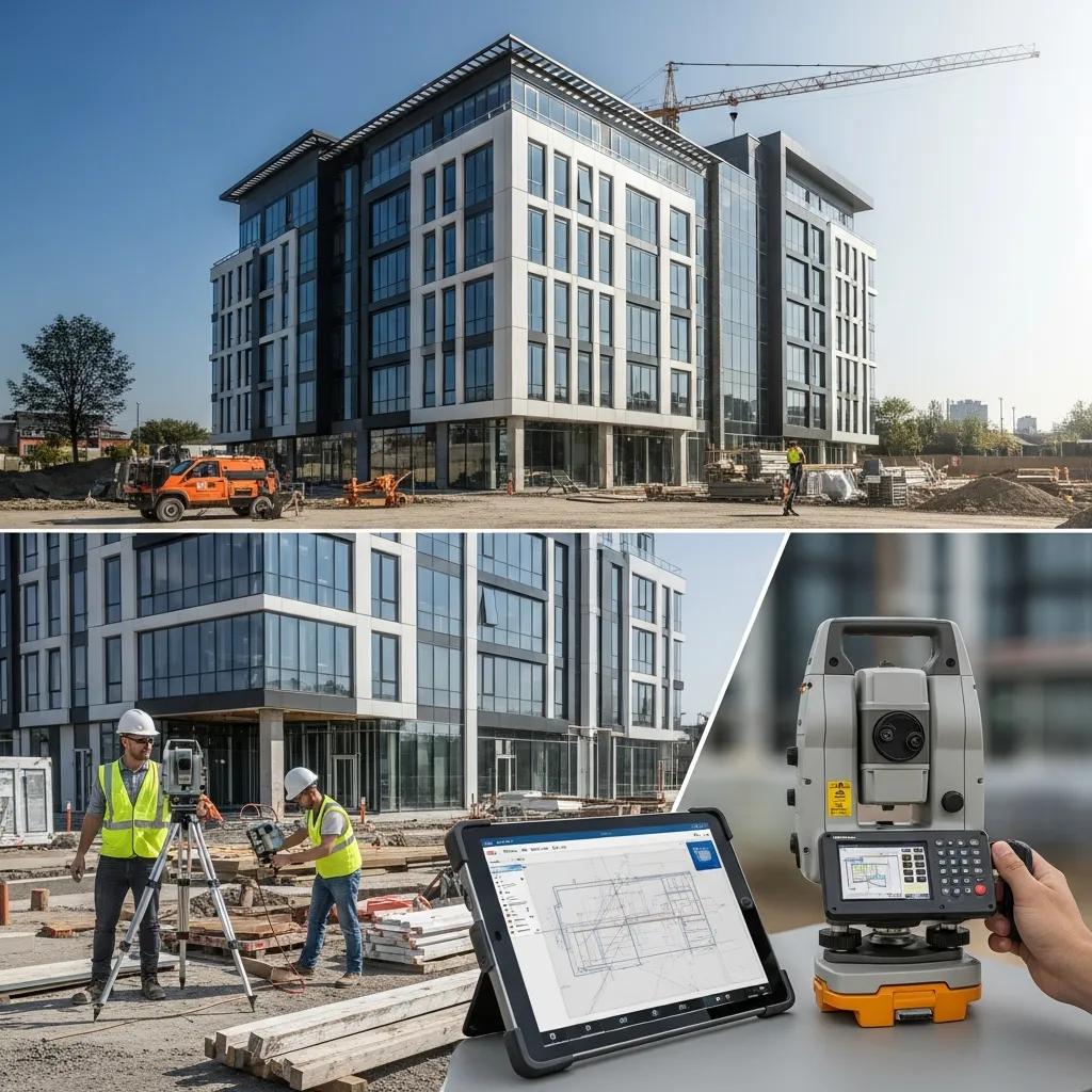
Case Study — Millimeter‑Accise Layout for a Commercial Office Fit‑Out Using VDC, BIM and Robotic Total Station Technology This case study shows how integrated field and digital workflows—Trimble Robotic Total Station, Virtual Design and Construction (VDC), coordinated BIM, and 3D laser scanning—delivered millimeter‑level accuracy and clear reductions in rework on a commercial office project. You’ll find a concise breakdown of the project challenges, the step‑by‑step RTS staking workflow tied to a federated model, how VDC and 4D sequencing avoided clashes, and how scan‑to‑BIM verified as‑built conditions. The content focuses on practical, measurable outcomes that matter to general contractors, MEP subcontractors, and owners pursuing predictable installs and faster commissioning. We map the flow from model validation to field staking and post‑install verification and highlight the workflow artifacts—clash reports, point‑cloud registrations, and coordinate exports—that supported each handoff. Throughout, discoverability keywords such as VDC office build, Robotic Total Station layout commercial, and scan‑to‑BIM commercial office are included to help search and relevance. Key challenges and project objectives This engagement was a mid‑rise tenant fit‑out where precise locations for MEP penetrations, anchor bolts, and overhead hanger systems were essential to hit tight commissioning windows and avoid costly rework. Our primary goals were millimeter‑level layout accuracy, fewer field clashes between trades, and a compressed installation schedule through coordinated sequencing. The team faced dense MEP routing in limited plenum space, multiple trades working in parallel, and work performed around occupied areas with minimal disruption. Meeting these constraints required a single coordinated coordinate source, regular clash detection cycles, and a field layout method directly tied to validated BIM deliverables to reduce ambiguity and rework risk. Client and project scope The client was a commercial building owner/general contractor running a tenant fit‑out and system upgrades where MEP, structural, and architectural work overlapped. Scope included MEP routing, anchor bolt placement for suspended ceilings, slab and wall penetrations, and precise locations for lighting and AV fixtures. Work took place across several floors with phased access, so staged layout and verification were necessary to align deliveries and trade sequences. This scope required close coordination between design teams, trade models, and field layout crews to ensure installations matched the coordinated BIM model. Precision and coordination challenges Critical tolerances centered on anchor bolt and hanger locations where small deviations can cascade into extended installation delays and assembly rework. Multi‑trade coordination risks included clashes between ductwork, conduit, and structural elements in tight plenums and interstitial zones. Unknown existing conditions on parts of the site required verification scans before layout to avoid late discoveries and change orders. These factors made accurate coordinate transfer from the federated model to the field—and frequent verification checkpoints during installation—essential to protect schedule and quality. How CCLS used Robotic Total Station for precise office layout RTS‑driven workflows translated model coordinates directly to the field by establishing a verified control network and reference points that linked BIM geometry to on‑site control for millimeter‑level staking. Our field crew set control points and instrument stations, registered the BIM coordinate system to those control points, and used the RTS to stake critical MEP, structural, and architectural locations. We ran verification passes after initial staking and again post‑install to confirm tolerances and generate traceable digital layout records. That process cut iterative measure‑and‑mark cycles, tightened QA/QC feedback, and allowed quick corrections when deviations occurred. Conway Coordination and Layout Services (CCLS) delivered the integrated service package on this job—Robotic Total Station layout, VDC construction services, BIM coordination, and 3D scanning—so the field and model teams worked from the same verifiable coordinates. Our exports, clash reports, and point‑cloud references were consistent across layout and model updates, simplifying handoffs between model managers and field crews. Aligning RTS staking with a federated BIM reduced ambiguity in installation instructions and produced digital records for owner acceptance and commissioning. Tool / Technology Characteristic Application Trimble Robotic Total Station Millimeter‑level accuracy tied to a control network Stake anchor bolts, hangers, and penetration points Federated BIM model Centralized coordinate source and clash documentation Export critical points and coordinates for layout 3D laser scanning Dense point cloud of existing and in‑progress conditions Verify deviations and update model as‑built Trimble Robotic Total Station’s role in achieving millimeter accuracy The Trimble RTS is a precision instrument that reads model coordinates and places points on site with millimeter‑level repeatability when tied to a verified control network. After registering the BIM coordinate system to field control, the RTS enables direct staking of hangers, anchors, and finish fixtures without manual interpolation. Accuracy depends on solid control geometry, correct instrument setup, and site conditions, but RTS workflows routinely meet the tolerances required for anchor bolt and service‑penetration layouts. That reliability reduces subjective field interpretation and keeps installations aligned to the coordinated model. How robotic layout reduces human error and speeds work Robotic layout cuts out many manual measurement steps, replacing tape‑and‑bubble workflows with coordinate‑driven staking that eliminates common errors like transcription mistakes and measurement drift. One operator can perform rapid stake‑and‑verify cycles, shortening layout time per floor and allowing more frequent verification within existing schedule windows. RTS digital records give QA traceability and support dispute resolution by comparing measured locations to modeled points. Those benefits add up to fewer rechecks, less rework, and a smoother installation cadence for trades. How VDC was integrated into the office build VDC served as the organizing discipline tying federated BIM review, clash detection, and 4D sequencing directly to field layout so model validation dictated when and where to stake. VDC established coordination cycles, produced clash reports, and aligned model‑based work packages with the schedule to guide staged layout and installs. By simulating installation sequences in 4D, the team identified access constraints and optimized the order of operations, letting the field plan control placement and layout windows proactively. That integration ensured model findings became immediate, actionable instructions for the field and reduced downstream surprises. The core VDC deliverables that coordinated layout and installation included: Federated clash reports: Regular runs to expose spatial conflicts before field work begins. 4D installation sequences: Time‑phased model elements aligned with
Navisworks Clash Detection Services in Charlotte, NC

Navisworks Clash Detection Services in Charlotte, NC: Expert BIM Coordination and Construction Clash Management Navisworks-driven clash detection brings models together and applies clear, rule-based checks to find and prioritize geometric and clearance conflicts before crews reach the field. For Charlotte projects, that means fewer surprises, lower RFI volume, and less schedule risk. Below we walk through how Navisworks detects clashes, why early detection matters for owners, GCs, MEP and structural teams, and how disciplined VDC practices turn model issues into field-verified layout. You’ll get practical workflows, the local technologies we commonly use (Autodesk Navisworks and Trimble Robotic Total Station among them), and a clear line from coordinated models to prefabrication and installation sequencing. Follow the step-by-step processes and checklists here and your team can move from model discovery to validated field placement with fewer delays and clearer responsibilities. What Are Navisworks Clash Detection Services and Their Benefits in Charlotte? Navisworks clash detection combines federated models, configurable clash tests, and structured reporting to catch hard intersections and clearance issues before construction starts — which saves time and money on Charlotte jobs. By aggregating discipline models and applying tolerance-driven rules, the process prioritizes what matters for installation. The payoff: fewer RFIs, smaller change-order risk, and better schedule performance for owners and GCs, plus less on-site coordination work for MEP and structural subcontractors. On dense urban projects or phased jobs in Charlotte — where mechanical corridors and access are tight — this proactive approach prevents reactive rework in the field. Navisworks clash detection delivers these key stakeholder benefits: Owner Benefits: Earlier conflict detection reduces RFIs and lowers the chance of costly change orders. General Contractor Benefits: Issues are resolved before crews mobilize, improving schedule reliability and cutting rework. MEP Contractor Benefits: Clearer coordination outputs speed shop drawing approvals and support prefabrication. The table below summarizes who gains what from early clash detection. Entity Attribute Value Owner Reduced RFIs Fewer design clarifications during construction General Contractor Improved schedule adherence Lower risk of installation delays and rework MEP Contractor Reduced field coordination time Faster shop drawing approvals and prefabrication readiness When teams invest in model-based clash management up front, they shift cost and schedule risk left — and set the project up for smoother coordination and field execution. Next: how Navisworks finds and helps resolve those clashes. How Does Navisworks Identify and Resolve Construction Clashes? Navisworks works by federating discipline models into a single coordination environment, then running clash tests that flag hard intersections, clearance violations, or routing conflicts. The workflow starts with importing author models (Revit, IFC, or point cloud meshes), validating geometry and naming, then applying rule-based tests with tolerances that separate hard clashes from soft or clearance issues. Detected clashes export as structured reports and issue lists that feed into common tracking systems or coordination packages. Typical resolution steps include tagging an issue, assigning a trade lead, and tracking fixes through re-validation runs until the clash is cleared. This detection-to-resolution loop links model review to tangible deliverables and a predictable cadence for coordination. Clear issue ownership and re-validation reduce ambiguity and let teams move confidently from model decisions to accurate field layout and verification. What Are the Advantages of Early Clash Detection for Charlotte Construction Projects? Finding clashes early prevents costly downstream fixes, streamlines procurement, and supports prefabrication strategies that save time on site. Early detection also improves sequencing so trade coordination is more predictable — clearance and routing questions are settled in the model rather than while crews are installing systems. On Charlotte jobs with tight MEP corridors, phased schedules, or constrained urban sites, those advantages translate to fewer installation conflicts, better labor utilization, and a cleaner path to turnover. Early clash detection also improves risk communication: owners and GCs gain clearer visibility into constructability concerns and can plan contingencies before they impact the schedule. From there, BIM coordination expands those benefits across MEP and structural teams. How Does BIM Coordination Enhance MEP and Structural Clash Detection in Charlotte? BIM coordination makes clash detection actionable by setting collaboration standards, preparing review-ready federations, and turning clash output into clear work packages for trades. Centralized models and issue tracking increase transparency between architects, structural engineers, and MEP leads, speeding design validation and shrinking the loop from detection to resolution. Standards — including LOD expectations, naming conventions, and clash severity rules — reduce false positives and keep the team focused on high-impact issues that affect installation. Well-run BIM coordination produces measurable outcomes in three areas: Fewer RFIs because design intent is clarified within coordinated models. Faster shop drawing approvals when federations are clash-free and support prefabrication. Less field rework because geometry is validated before procurement and installation. These results depend on repeatable processes and tools that carry model validation through to trade-level execution, which we outline below. What Role Does BIM Play in Streamlining Construction Coordination? BIM is the common language for interdisciplinary coordination: a visual, data-rich model everyone can review together. Regular coordination meetings using federated models let teams visualize conflicts, set priorities, and agree on routing or design adjustments before fabrication. Integration with project-management and issue-tracking platforms keeps assignments visible and enforces accountability, while standardized model handoffs preserve consistency for repeatable clash testing. By turning design intent into documented coordination actions, BIM reduces misunderstandings between design and construction teams and enables efficient MEP and structural coordination using Navisworks as the aggregation and testing platform. How Are MEP and Structural Components Coordinated Using Navisworks? Navisworks gives teams practical tools — model sectioning, clash grids, rule-based tests, and saved viewpoints — to localize clashes and clearly communicate solutions. A typical checklist includes importing authoring files (Revit, IFC), validating geometry and levels, running prioritized clash tests (hard, clearance, proximity), grading and filtering results, and exporting reports for trade action. Issue lifecycle control requires re-running validation tests after updates to confirm fixes and preserve model integrity. Those steps produce clear deliverables — clash reports, updated federations, and verified viewpoints — that inform shop drawings, prefabrication, and field layout. Consistent execution of this routine helps translate
MEP BIM Modeling Services in Savannah, GA

MEP BIM Modeling Services in Savannah, GA — Precise Coordination for Predictable, On‑Time Delivery MEP (mechanical, electrical, plumbing) Building Information Modeling (BIM) delivers coordinated, data-rich models that help teams find clashes early, quantify materials, and guide accurate installation from design through commissioning. Below we explain how disciplined MEP BIM modeling and coordination reduce rework, shorten schedules, and improve cost certainty for projects in Savannah and the surrounding region. You’ll find trade-specific benefits, a typical clash-detection workflow, and how scan-to-BIM plus precise field layout connect the digital model to what gets built on site. If you’re a local contractor, engineer, or owner tackling renovations, historic restorations, or tight urban sites, this practical overview shows how BIM de-risks projects and produces prefabrication- and fabrication-ready outputs. The sections that follow cover core benefits, HVAC/plumbing/electrical details, local service options, enabling technology, an end-to-end process from concept to as-built, VDC integration, and common technical questions about tools and Level of Development (LOD). Conway Coordination and Layout Services (CCLS) is a Savannah-based provider offering BIM modeling and coordination, 3D scanning, VDC consulting, and survey-grade field layout — services that tie model geometry to construction execution. We follow industry-standard BIM workflows and pair them with field technology to deliver fabrication-ready files and to validate installations on site, smoothing handoffs between design, fabrication, and crews. Continue for concise checklists, a step-by-step process guide, and clear tables that map services to deliverables and client outcomes for easy decision-making on local projects. Why MEP BIM Modeling Matters for Construction in Savannah MEP BIM gives project teams a single authoritative model for mechanical, electrical, and plumbing systems so spatial conflicts are identified early and their schedule and cost impacts can be measured. When discipline models are aggregated into a federated model, clashes are found before crews arrive, improving constructibility and cutting RFIs during installation. Savannah projects often involve retrofits and historic elements; BIM provides accurate context for routing and prefabrication so teams avoid on-site surprises. The next section explains trade-specific gains for HVAC, electrical, and plumbing, and how those gains stack up when coordination is done across trades. MEP BIM produces repeatable outputs that translate into measurable project improvements: Less rework and fewer RFIs through early clash resolution and verified clearances. More predictable schedules through prefabrication and better sequencing. Tighter cost control thanks to accurate quantity take-offs and material lists. Together, those benefits turn BIM into a practical risk‑reduction strategy that improves installation accuracy and operational readiness for owners. How MEP BIM Coordination Helps Mechanical, Electrical, and Plumbing Systems Coordination in a BIM environment ensures each trade’s geometry, clearances, and system requirements are reconciled before field work begins—making systems easier to install. For HVAC, BIM streamlines duct routing, reduces complex transitions that hurt airflow, and resolves clashes with structure and architecture. Electrical modeling clarifies conduit and tray runs, panel locations, and lighting layouts to meet code and serviceability needs while avoiding late design shifts. Plumbing coordination verifies slopes, drainage routes, and fixture connections so prefabricated spools fit as intended. These trade-level improvements cut field labor hours and compress commissioning by preventing the surprises that typically consume project float. Model-based coordination also creates consistent software-driven outputs for procurement and fabrication, supporting modular construction and shop-ready deliverables when teams choose to prefabricate. How Clash Detection Reduces On‑Site Rework and Improves Accuracy Clash detection compares federated discipline models to reveal geometric conflicts—like two elements occupying the same space—so issues are resolved in design or preconstruction rather than in the field. A typical clash cycle follows four steps: aggregate models, run automated scans, classify and prioritize clashes, then drive resolution and verify fixes with re-runs. For example, a duct‑to‑beam clash is assigned an owner, scheduled for the next coordination meeting, and checked in the updated federation to confirm closure. Teams that run regular clash cycles see fewer field changes, reduced RFIs, and measurable cuts in rework labor and cost overruns. A disciplined clash workflow also produces data-rich reports linking each issue to model elements, responsible parties, and status—so project managers can turn clashes into tracked actions and measure installation time saved. Which MEP BIM Services Does CCLS Provide in Savannah, GA? CCLS delivers an integrated suite of services that bridge model authoring, coordination, and field layout, helping Savannah projects move smoothly from design to installation and turnover. Our services include HVAC, plumbing, and electrical BIM authoring and coordination; iterative clash detection and multi‑trade coordination; scan‑to‑BIM and as‑built models from point clouds; fabrication support and shop‑drawing readiness; and survey‑grade field layout. The list below summarizes core offerings and how they plug into project workflows. HVAC, plumbing, and electrical BIM model authoring and coordination. Iterative clash detection and facilitation of coordination meetings. Point‑cloud capture and conversion to accurate as‑built BIM models. Fabrication‑ready outputs and support for shop drawings and spool production. These services translate design intent into verified installation geometry, reduce installation errors, and support prefabrication strategies that speed schedules and lower on‑site labor exposure. Quick reference: the table below maps each service to typical deliverables and client benefits for fast evaluation. Service Deliverable / Attribute Client Benefit HVAC BIM Modeling Coordinated duct and equipment models Less duct rework and better airflow performance Plumbing BIM Coordination Routed pipework with slope and fixture integration Fewer site adjustments and fabrication‑ready spools Electrical BIM Modeling Conduit/tray routing and equipment layouts Code‑compliant installations with fewer RFIs 3D Scanning & Scan-to-BIM Registered point clouds and as‑built models Accurate existing‑conditions documentation for retrofits Clash Detection & Coordination Clash reports and tracked issue lists Early conflict resolution and reduced field rework How HVAC BIM Modeling Improves Ductwork and Equipment Coordination HVAC BIM creates accurate equipment families and spatially correct ductwork that respect clearances, access, and structural interfaces—improving constructibility before crews mobilize. By modeling transitions, diffusers, and service zones, teams can optimize routing to lower material costs and preserve performance metrics like airflow and pressure drop. In Savannah retrofit projects, extracting obstacles from point clouds prevents late redesigns and keeps equipment access for maintenance. Typical deliverables include coordinated layouts, installer notes, and clash-checked geometry
Conducting Life Cycle Assessment for Green Buildings

Conducting Life Cycle Assessment for Green Buildings: Comprehensive Guide to Sustainable Construction Life Cycle Assessment (LCA) for buildings is a repeatable method for measuring a project’s environmental impacts from material extraction through construction, occupancy, and end-of-life. This guide lays out why LCA matters for reducing embodied and operational carbon, meeting certification and procurement expectations, and steering design and purchasing choices that cut real-world impact. Owners, designers, and contractors face growing regulatory and market demands for verifiable whole‑life carbon reporting; here we show how to plan, run, and fold LCA into digital workflows using BIM, VDC, and 3D scanning. Read on for the four LCA stages, practical data sources (EPDs, inventories, metering), how BIM/VDC supply LCI inputs, strategies to lower embodied and operational carbon, and which certification systems expect LCA evidence. We also map common tools and standards (ISO 14040/14044, One Click LCA, Tally) to everyday workflows and explain how precise layout and digital coordination reduce waste and improve LCA accuracy. What is Life Cycle Assessment and Why is it Essential for Green Buildings? Life Cycle Assessment (LCA) is a standardized approach—defined by ISO 14040 and ISO 14044—for measuring environmental impacts across a building’s life. It starts with a life cycle inventory (LCI) of material and energy flows, converts those flows into impact categories through life cycle impact assessment (LCIA), and ends with an interpretation that informs design or policy decisions. LCA matters because it gives project teams quantifiable, cradle‑to‑grave evidence to cut carbon, conserve resources, reduce waste, and meet evolving whole‑life carbon rules. Practitioners rely on LCA tools (One Click LCA, Tally) and Environmental Product Declarations (EPDs) as primary data inputs. There are four core LCA stages (summarized below). Understanding them helps teams target the most effective interventions for both embodied and operational impacts. LCA is valuable for buildings because it enables: Balanced decision‑making between embodied and operational carbon. Compliance with certification and procurement requirements. Identification of high‑impact materials and processes for focused reductions. This baseline definition sets up the detailed stage breakdown that follows and shows how LCA outputs translate into design and procurement changes. What are the key stages of Life Cycle Assessment in construction? The four backbone stages of a construction LCA are: goal and scope definition, life cycle inventory (LCI), life cycle impact assessment (LCIA), and interpretation. Goal and scope establish system boundaries (cradle‑to‑gate, cradle‑to‑grave, or whole life) and the functional unit (for example, kg CO2e per m²‑year), clarifying what we measure and why. The LCI compiles quantities—materials, embodied energy, transport distances, manufacturing processes, and on‑site activities—that feed into LCIA to produce impact indicators like global warming potential. Interpretation identifies hotspots, uncertainty, and trade‑offs and turns results into actionable recommendations for design, procurement, or operations. Use this practical checklist to prepare each stage: Agree on the functional unit and system boundaries. Gather material quantities and EPDs for the highest‑impact assemblies. Document transport, installation, use‑phase energy, maintenance, and end‑of‑life scenarios. Following this checklist readies teams for accurate inventory collection and highlights how BIM and VDC become key data sources. How does LCA contribute to reducing environmental impact in buildings? LCA pinpoints where interventions yield the largest reductions and supports trade‑off analysis between embodied and operational carbon. For example, an LCA can show whether adding insulation—raising embodied carbon slightly—reduces enough operational emissions over the building’s life to be worthwhile. Concrete and steel often dominate embodied carbon; strategies like specifying low‑carbon concrete mixes, increasing recycled content, or switching to lighter cladding can cut lifecycle emissions. LCA also captures the benefits of prefabrication and modular construction by quantifying reductions in on‑site waste and rework. Typical outcomes from LCA‑driven choices include material substitution, refined assembly sequencing, and targeted energy upgrades. Locking those decisions into procurement and design standards closes the loop between analysis and measurable environmental improvement. How Do BIM and VDC Technologies Support Accurate Life Cycle Assessment? BIM, VDC, and 3D scanning deliver the element‑level data LCA requires: precise material quantities, explicit assembly definitions, and searchable metadata. BIM breaks a building into quantifiable elements that map directly to life cycle inventory inputs. VDC coordinates sequencing and prefabrication to reduce on‑site waste, improving LCA fidelity. 3D scanning verifies as‑built conditions and flags deviations that can otherwise skew inventories, strengthening LCA accuracy and post‑occupancy validation. Typical BIM‑to‑LCA workflows involve model classification, attribute tagging, and export to LCA tools. Below is a practical mapping of common BIM/VDC deliverables to their LCI relevance. BIM and VDC outputs align directly with LCI inputs and validation steps. BIM/VDC Deliverable LCA Attribute How it becomes LCI Input Element quantity schedules Material mass/volume Converted to kg using material density and mapped to emissions factors Material property tags Material type, recycled content Matched to EPDs or inventory databases for embodied impacts Federated clash‑resolved model Confirmed assemblies Reduces double‑counting and missing components in the LCI 3D as‑built scans Installation deviations Update the LCI to reflect actual material use and waste This mapping shows how digital deliverables reduce uncertainty and feed reliable inputs into LCA tools, enabling more trustworthy whole‑life carbon assessments. What role does Building Information Modeling play in LCA data collection? BIM is central because it structures element geometry and metadata so material takeoffs become traceable LCI inputs. A well‑authored BIM model includes material tags, assembly codes, and quantities that LCA software can interpret—provided classification standards and naming conventions are consistent. Key attributes are material type, density, thickness, and product identifiers that link to EPDs or manufacturer data. Common pitfalls are inconsistent naming, missing metadata, or oversimplified assemblies that hide constituent materials; these gaps increase LCI uncertainty. Adopting modeling standards, attribute templates, and a handoff protocol for LCA makes BIM an authoritative inventory source and prepares teams for the next step: how VDC reduces waste recorded in the LCA. How does Virtual Design and Construction optimize workflows for sustainability? VDC lowers environmental impact through clash detection, sequencing optimization, and prefabrication planning—all of which reduce rework and material waste. Clashes identified in federated models prevent on‑site fixes that consume extra materials and labor. Sequencing simulations improve delivery timing and
BIM-Based Layout Planning in Raleigh, NC

BIM-Based Layout Planning in Raleigh, NC: Exact, Model-Driven Layouts to Keep Your Project on Time BIM-based layout planning turns coordinated digital models into reliable field coordinates so crews place structural and MEP elements to millimeter tolerances. This guide explains how model-to-field workflows—combining BIM, VDC, 3D scanning, and robotic total stations—bring design accuracy to Raleigh job sites, cut rework, and speed installations. You’ll get straightforward explanations of model LOD and metadata transfer, practical pre-construction sequencing with clash detection, and real-world use cases for healthcare, commercial, industrial, and historic preservation projects in Raleigh. We also outline a point-cloud → BIM → verified-layout workflow, the measurable ROI drivers to watch, and how Conway Coordination and Layout Services (CCLS) partners with project teams across the Southeast to deliver coordination, layout, and verification. Practical checklists, comparison notes, and concise action steps are included so contractors and owners can apply BIM layout planning and reduce schedule risk. What is BIM-Based Layout Planning and How Does It Benefit Raleigh Construction Projects? BIM-based layout planning is the process of pulling coordinated geometry and element metadata from a model, checking it for constructability, and exporting field-ready coordinates that guide onsite placement. The workflow depends on accurate 3D geometry, an agreed LOD for layout (commonly LOD 300–350), and clean data exchange so robotic total stations can place model-driven points in the field. For Raleigh teams, the biggest payoff is repeatable placement accuracy that reduces fit issues, lowers rework, and shortens installation cycles for critical trades. That’s why integrating BIM coordination, clash detection, and model-to-field delivery is central to reliable pre-construction planning and efficient sequencing on local projects. The list below sums up the most tangible benefits Raleigh teams see when they adopt BIM layout planning and points to where to start. BIM-based layout planning produces measurable gains on Raleigh projects through better coordination, fewer field errors, and more predictable schedules. Expect these primary advantages: Improved Accuracy: Model-driven layout delivers millimeter-level placement for anchors, embeds, and MEP points. Reduced Rework: Early clash detection prevents many in-field corrections and costly change orders. Faster Schedule: Precise layout accelerates installation and shortens trade handoffs. Better Fabrication Readiness: Coordinated models make prefabrication and off-site assembly more reliable. Safer Worksites: Fewer layout iterations reduce exposure to corrective work and hazards. Combined, these outcomes lower total project cost and increase schedule certainty. Teams using BIM layout planning typically see fewer RFIs and steadier construction sequencing—setting the stage for the tools and standards that make model-driven workflows repeatable on site. Defining BIM-Based Layout Planning: Concepts and Technologies At its core, BIM-based layout planning relies on three elements: a coordinated 3D model, a clear LOD and metadata standard, and a dependable data path to the field instrument. Models from Revit or similar platforms contain the geometry and attributes that become layout points; export formats and model-checking tools align coordinate systems and tolerances. Naming conventions and data-exchange standards make sure items like anchor bolts or MEP sleeves map to field deliverables without guesswork. The model-to-field loop looks like this: model validation → clash detection → coordinate export → field verification. That sequence is the technical foundation for reliable BIM layout planning in Raleigh. With those basics in place, the next section shows how these practices translate into real cost and schedule improvements for developers and contractors. Key Advantages for Raleigh Developers and Contractors: Cost Savings and Accuracy Accurate, model-driven layout reduces onsite uncertainty by catching clashes earlier and translating model precision to the field—delivering direct savings in time and cost. Early coordination cuts the number of rework events and the associated labor and material waste. For example, resolving a single structural–MEP interference in the model can prevent days of installation delays and tens of thousands in corrective costs on a medium-sized project. Quantifying these impacts helps owners and contractors prioritize BIM coordination in pre-construction and plan sequencing to capture those savings. These scenarios show why layout accuracy matters for tolerance-critical tasks like anchor bolt placement and MEP routing, and they lead naturally into the implementation steps that realize these gains on active jobs. If you want hands-on support applying these practices on Raleigh projects, Conway Coordination and Layout Services (CCLS) provides integrated BIM modeling and coordination, VDC consulting, 3D scanning, and robotic total station layout. Based in Loris, SC, we serve the Southeastern U.S. including North Carolina and bring family-owned responsiveness to model-to-field execution. Contact CCLS to discuss scope, verification needs, and how we can support your next Raleigh build. How Does CCLS Integrate BIM, VDC, and Robotic Total Stations for Superior Layout Accuracy in Raleigh? Model-to-field accuracy depends on disciplined VDC coordination, validated models, and precise field execution. Our applied workflow stitches those pieces together into repeatable steps for Raleigh sequencing: ingest the models and run clash detection to resolve multi-discipline conflicts, extract coordinates tied to project control, format data for robotic total station import, verify control points in the field, then execute layout. The final—and critical—step is closing the loop: capture as-built points with scanning or total-station checks and reconcile them with the BIM so the model stays current during construction. That stepwise approach reduces surprises and makes layout deliverables both constructible and verifiable. Below is a concise workflow summary the majority of teams follow when adopting a model-driven layout strategy. Model Validation: Combine discipline models and run clash cycles to set a coordinated baseline. Coordinate Export: Pull layout points with required tolerances and attribute data for field use. Field Setup and Layout: Establish project control, import coordinates into a Trimble robotic total station, and execute model-based points. Verification and Update: Capture as-built points via 3D scanning or total-station checks and reconcile with the BIM for ongoing coordination. This sequence reduces back-and-forth between office and field, tightens construction sequencing, and supports prefabrication and efficient installation cycles. The table below clarifies each tool’s role in the integrated model-to-field workflow and why it matters for accuracy and coordination. Tool / Technology Primary Attribute Typical Application BIM Model (Revit) Coordinated geometry & metadata Source of layout coordinates and fabrication data